Download
1 / 19
190 likes | 286 Views
Target wheel eddy current modelling. James Rochford On behalf of the Helical collaboration. Introduction. Introduction From previous modelling Good confidence in VF Electra solutions Now have agreement with Carmen models

E N D
Target wheel eddy current modelling James Rochford On behalf of the Helical collaboration STFC Technology
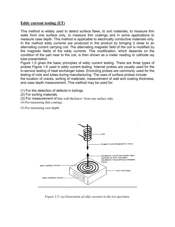
Introduction • Introduction • From previous modelling • Good confidence in VF Electra solutions • Now have agreement with Carmen models • Now evident simple electra wheel rim models behave quite differently to the real wheel. • Presence of the spokes makes a considerable difference to the predicted torque • Have only run model at slow speed 100rpm • Have done preliminary scaling the results • Here will present a summary of the latest results • Outline next steps
Previous models • Introduction • From previous modelling • LLB disk experiment results • Electra models • Good agreement with data Eddy currents A/mm2 @2000rpm
VF electra solutions • VF electra solutions • Have confidence in Electra solutions • Here look at inclusion of coils &iron • Model 1:Simple ring, coils only • Model 2:Simple ring , coil and iron • Field distribution different • Model constructed to have same Model 2 & 3 Model 1
VF electra solutions • VF electra results • Simple spread sheet estimate Good agreement
VF electra solutions • VF Electra results • All models agree well • Predict same torque and power dissipation • Both these models agree with • simple spread sheet estimates • For a speed of 100rpm • Electra prediction model 3 • Retarding torque of 7000 N.mm • Power dissipation of ~0.07kW.
VF electra solutions • Eddy distribution from Electra models • Both models give consistent current distrobutions Models 2&3: Gradient steeper dB circulation paths compressed and greater peak current. Model 1: Gradient not so steep and dB lower - circulation path elongated and lower peak currents.
Carmen spoke model • Description • Having under stood the Electra solutions and gained some confidence in the solution a Carmen model was constructed which includes the spokes • The CARMEN solver, has the capability to solve the full dynamic problem i.e the motion coupled to the electromagnetic solution and does not need any rotational symmetry in the problem. • A sacrificial mesh layer , “the gap” around the rotating region is re-meshed for all points in the solution • Meshing needs to be adequate to model current distribution and robust enough to allow the gap to be re-meshed at all points in the solution whilst giving consistent solutions Mesh distribution in wheel
Carmen spoke model • Model results; part revolution 0o-60 o • Run a number of Carmen solutions to look at the effect of step time on the problem solution • The effect of time not so critical can see step 2deg starts to deviate from 1deg solution- problem computationally very expensive. • In these solutions we see the force increases by a factor of 7 @ 100rpm w.r.t the Electra simple wheel rim prediction. • Is this real is it caused by the spokes? • Retarding torque predicted by CARMEN for 100rpm for a part revolution
Carmen spoke model • Model results; full revolution • Here a full rotation is run But the solution step is every 2 deg but the mesh is slightly cruder • So solution not quite as accurate as part solutions • But you can clearly see 5 equally spaced peaks in the torque • Rem; wheel has 5 spokes • Between peaks Torque drops to a value comparable with the Electra solution. • Retarding torque predicted by CARMEN for 100rpm for a full revolution
Carmen spoke model • Model results; full revolution • Here we see the torque peaks correspond to each point a spoke crosses the –ve X axis i.e. when a spoke passes through the coil centres 90o 162o 18o rotation 234o 18o 162o 234o 306o 90o 306o • Retarding torque predicted by CARMEN for 100rpm for a full revolution Alignment at t=0
Carmen spoke model • Why does the torque increase? • The reason becomes evident once one looks at the eddy current distributions • What happens is the spokes rotate they create additional current paths, all the paths meet in the center and return via the central spoke it passes the coil centre. • This current gives rise to large Ix (~600A) along the spoke coupled to the BZ field generates a large Fy giving rise to a larger retarding torque. • In between the spoke transit the current distribution reverts to one similar that seen in the Electra models. In this case the currents down the spokes are ~80 amps and the torque generated by each spoke should cancel. I-1 I-2 I-0 I-3 I-4 I-0=I-1+1-2+I-3+I-4=590A I-1=I-4=265A 1-2=I-3=30A
Carmen spoke model • Movie showing eddy currents a wheel rotates • Note the increase of currents in the R.H.S of the wheel as the spoke passes the coil centerline
Carmen spoke model • Off axis torques Tx • By symmetry there should be no torque about the X axis. • This is what the models show
Carmen spoke model • Off axis torques Ty • There may be a torque about Y causing the wheel to “jitter”. This could be generated by a nett Fz in the interaction region. • The models indicate there may be a significant Ty, • However the full revolution model (purple curve) seems to be too crude to resolve this, but the more accurate part revolution models seem to show something • It looks like we generate ~+(2-3)N.m as the spoke approaches the coil centre and switching to –(2-3)N.m as it recede from the coil centre • This is small @ 100rpm, and should scale with the speed, I would expect ~+/-(40-60)N.m @2000 rpm . • This is not huge, I may cause the wheel to jitter? • Additionally over time it may cause significant wear in wheel bearings, particularly at higher speeds?
Carmen spoke model • Power dissipation • Whilst Electra predicts a power of 0.07kW to continually drive the wheel rim through the field @ 100rpm. • Carmen predicts additional power of 0.32kW is needed by the spokes as they pass through, creating peaks of .39kW. • This increases the average power to something like 0.2kW • i.e. more than double the Electra prediction
What happens at higher speeds? • Extrapolating the results • Higher speeds • The torque is directly proportional to the rotational speed • At 100rpm we see torque peaks of ~40N.m • So at 2000rpm one would expect torque peaks of ~800N.m This is large (Rem Electra value was ~110N.m from the rim) • The power dissipation goes as the square of the rotational speed • Whilst Electra predicts a power of 0.07kW to continually drive the wheel rim through the field @ 100rpm. • Carmen predicts mean power of 0.2kW is needed by the spokes as they pass through. Peaking at 0.4kW • So @2000rpm from simple scaling we get mean power of 80kW, this seems rather large ?? i. • I will need to run some high speed models to investigate this • Greater immersion depths • In this model just the rim is immersed in the field • Things will get worse with greater immersion depths. • This needs investigation
Potential fix • Is there a way around the problem? • The spokes seem to have a big effect. • To eliminate these problems it is suggested that insulating breaks are inserted in the spokes, if possible. • Schematic below outlines suggestion • Is this feasible in the current scheme? axis Insulator Wheel rim Outer spoke Inner spoke
summary • Conclusions • The spokes have a considerable effect at 100rpm • The simplistic extrapolation to higher speeds is pessimistic and needs to be confirmed. • It seems that although the spikes in the torque are short lived they are quite significant and at high speeds could be problematic. • Next steps to run model at higher speeds to confirm simple extrapolations. • Run 1 model to investigate immersion depth • To eliminate these problems it is suggested that insulating breaks are inserted in the spokes, if possible.