Download
1 / 35
360 likes | 621 Views
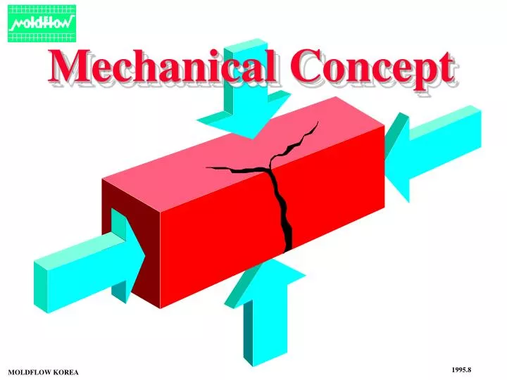
Mechanical Concept. 1995.8. MOLDFLOW KOREA. Mechanical Concept. UNIT. mass length time force pressure. SI kg m sec N Pa. Metric kg mm sec kgf kgf/cm 2. English lb in sec lbf psi. Mechanical Concept.

E N D
Mechanical Concept 1995.8 MOLDFLOW KOREA
Mechanical Concept UNIT mass length time force pressure SI kg m sec N Pa Metric kg mm sec kgf kgf/cm2 English lb in sec lbf psi
Mechanical Concept Examples for UNIT SI Metric English 1 N 9.8 N 4.448 N 0.102 kgf 1 kgf 0.453 kgf 0.225 lbf 2.206 lbf 1 lbf Force 1 MPa 0.1 MPa 6.9 kPa 10.2 kgf/cm2 1 kgf/cm2 0.07 kgf/cm2 145 psi 14.22 psi 1 psi Pressure Pa = N / m2 psi = lb / in2
Mechanical Concept L Stress : S = P / A Strain : / L L Stress & Strain A ( m2 or cm2 ) L P ( N or kgf ) Unit : N/m2 = Pa (kgf/cm2 ) Unit : %
Mechanical Concept Ductile Fracture Brittle Fracture Strain-Stress Curve (1) Elastic Plastic Yield Point Tensile Strength = Stress at Yield Break Point Elastic Limt E Proportional Limit Tensile Strength = Stress at Break
Mechanical Concept Material-A E = Material-B Stress-Strain Curve (2) Strain Energy ; Toughness Toughness Material A > Material B Strength & Stiffness Material A < Material B
Mechanical Concept Examples for Tensile Properties Tensile Strength (73F,lb/in2) Modulus (73F,b/in2X106) Acetal ABS Nylon Polycarbonate Polyethylene Polyester PMMA PPO Polypropylene Polystyrene Polysulphone PVC 10 4 - 8 8 - 12 8 - 10 1 - 6 8 - 10 8 - 11 8 - 10 4 - 6 5 - 11 9 - 10 5 - 9 0.5 0.2 - 0.5 0.2 - 0.4 0.3 0.02 - 0.2 0.3 - 0.4 0.4 0.2 0.4 - 0.6 0.4 0.3 - 0.6
Mechanical Concept H H Poisson's Ratio () H / H L / L L L Poisson's Ratio
Mechanical Concept Examples for Poisson's ratio 0.28 - 0.29 탄소강 알루미늄 콩크리트 유리 Rubber Most Crystalline & Glassy Polymer Eng. Plastics 0.33 0.19 0.25 0.49 - 0.50 0.25 - 0.33 0.35 - 0.40
Mechanical Concept Principal Stress Normal Stress Principal Stress = Max. Normal Stress Shear Stress Shear Stress is zero on this Surface Surface
Mechanical Concept Mohr Circle + y x' y yx y +yx xy x'y' x'y' x' x x x xy 2 1 y -
Mechanical Concept Principle Stress prin-1xyxyxy prin-2xyxyxy [Example ] xy xy
Mechanical Concept V.MISES> Y Criterion for Yield 1. Von Mises Stress V.MISES ( Shell Element )
Mechanical Concept tresca = | max min| Criterion for Yield 2. Tresca Criterion + max 2 1 tresca> Y -
Mechanical Concept = / l Shear Stress Shear Rate Shear Stress = Shear force / Area l = G #Shear Modulus G
Mechanical Concept Shear Stress P Shear Modulus = 0.5 - 0.6 X Tensile Modulus @ Von-Mises ; 0.6 Tresca ; 0.5 전단면 위의결과는Yield Point 기준
Mechanical Concept Bending Stiffness M M Flexural Rigidity = E I Neutral Axis y @ E : Tensile Modulus @ I : Moment of Inertia Compression x Tension
Mechanical Concept M = P L Smax = M / Z Ymax = PL3/3EI M : Moment I : Moment of Inertia Smax : Max. Stress Ymax : Max. Deflection Z : = I / C Moment Position A ( Max. Moment & Stress ) P Ymax L C
Mechanical Concept P P P Examples for Moment with Various Boundary condition L L L M A X I M U M S T R E S S 1 1/4 1/8 M A X I M U M S T R E S S P O S I T I O N at Center & Support at Support at Center
Mechanical Concept Moment of Inertia I = A y2 dA y Neutral Axis Moment of Inertia Deflection w t 100 100 r 274 36.5 h 4600 2.17 w=101.6, t=3.18, r=4.76, h=22.22
Mechanical Concept L L Examples for Moment of Inertia Thickness = L/4 1 0.59 0.55 0.33 L L L L L L 100 wt 78 wt 34 wt 50 wt 0.66 0.51 0.91 0.91 L L L L L L L L 78 wt 63 wt 63 wt 63 wt
Mechanical Concept T1 L L / L T2 - T1 CV = Coefficient of Thermal Expansion L L T2 Heating ( Unit : mm/mm/degC ) Sthermal = CVX E)T2X ( T2 - T1 )
Mechanical Concept Examples for Coefficient of Thermal Expansion Coefficient of Thermal Expansion (x10-5,in/in/C) Acetal ABS Nylon Polycarbonate Polyethylene Polyester PMMA PPO Polypropylene Polystyrene Polysulphone PVC 8.1 9.0 8.3 6.5 12.0 6.0 7.0 5.2 5.8 6.0 5.4 10.0
Mechanical Concept l Creep ( under Load control ) t = hour t = 0 High Temperature APPARENT MODULUS TIME (HOURS)
Mechanical Concept Stress Relaxation ( Under Displacement Control ) l1 High Temperature t = 0 l1 =l2 APPARENT MODULUS l2 TIME (HOURS) t = hour
Mechanical Concept Examples for Tensile Creep Modulus Applied Load (lb/in2) Creep Modulus (73F,b/in2X103) 1 hr 100 hr 1000 hr Acetal ABS Nylon Polycarbonate Polyethylene Polyester PPO Polypropylene Polystyrene Polysulphone PVC 1500 1000 1500 3000 1000 1000 1500 1000 1500 4000 1000 390 295 160 345 50 440 430 165 135 350 330 280 255 115 320 30 400 400 90 20 320 280 250 210 100 310 25 380 320 65 10 310 180
Mechanical Concept Fatigue Failure ( S-N Curve ) Cyclic Loading Load (kg/mm2 ) Load 400 300 Time 200 100 103 104 105 106 Cycle
Mechanical Concept Examples for Fatigue Data Load ( lb/in2 ) Acrylic Acetal PC PVC ABS 12000 9000 6000 3000 0 102 103 104 105 106 107 Cycle
Mechanical Concept Velocity = m/sec Weight = kg Load Energy Impactor Load (kg) & Energy (kg.m) Plastics Time (msec) Impact Resistance ( Dynamic Failue )
Mechanical Concept Impact (continued) Factor of Impact 1. Stiffness 2. Mass 3. Course & Velocity Impact Load Static Load Force (N) If TL > (5-6) Tn , Loading Type = Static ( @ Tn : Natural Frequency ) tL)1 tL)2 Time (sec)
Mechanical Concept Failure Type Rapid Deformation Impact (continued) 1. Elastic Deformation higher than Yield Strength 2. Permanent Deformation 3. Tearing 4. Fracture 1. Fast Loading Rate 2. Rate Sensitivity of Mechanical Properties
Mechanical Concept W Coefficient of Friction When Max. Angle with no sliding Friction Force) F = N S @ : Corfficient of Friction (Static) N : Normal Force : Angle of Friction S F N
Mechanical Concept s k s k s : Static Friction Coefficient : Kinetic Friction Coefficient k Examples for Coefficient of Friction Steel on Polymer Polymer on Polymer Acetal Nylon Polycarbonate Polyethylene (LD) Polyethylene (HD) PET PTFE PVC PVDC 0.14 0.37 0.60 0.27 0.18 0.29 0.10 0.45 0.68 0.13 0.34 0.53 0.26 0.10 0.28 0.05 0.40 0.45 - 0.42 - 0.33 0.12 0.27 0.04 0.50 0.90 - 0.35 - 0.33 0.11 0.20 0.04 0.40 0.52
Mechanical Concept Hardness - Indentation Test P - Stiffness - Wear & Scratch if Hardness-A >> Hardness-B ( ex. Steel >> Polymer ) Abrasive Wear
Mechanical Concept V V Acetal, Nylon, PC, PVC,PPO Wear Abrasive Wear Adhesive Wear Abrasive Resistance ABS, PP PE, PS