Download
1 / 49
490 likes | 497 Views
This paper discusses the construction of Elmore-based Y-routing trees and the fidelity of delay estimators in the context of signal delay estimation in VLSI circuits. The authors compare different heuristics and evaluate their accuracy and relative performance. The findings provide insights into improving circuit speed and signal delay measurement.

E N D
Revisiting Fidelity: A Case of Elmore-based Y-routing Trees Tuhina Samanta*, Prasun Ghosal*, Hafizur Rahaman* and Parthasarathi Dasgupta† *Bengal Engineering & Science University, India †Indian Institute of Management Calcutta, India ` SLIP 2008, Newcastle
Outline • Y-Routing and Y-Routing Trees • Fidelity of Delay Estimators • Some Previous works • Motivation of our work • Construction of Elmore-based Y-Routing tree • Fidelity and Rank Correlation • Experimental Results • Conclusions SLIP 2008, Newcastle
Routing – a critical step • For a given set of terminals, connect different subsets (nets) of these terminals • Cost components to be minimized • wire length • number of layers • via • delay • Some recent Challenges in DSM Physical Design • Dominance of interconnect length • Congestion • Parasitic effects • Thermal effects SLIP 2008, Newcastle
Steiner trees for Routing • Involves the addition of a set of Steiner points to a given set of demand points (terminals) to generate an interconnection (with minimum wire-length, etc.) • Traditional Manhattan routing allows edges in only two directions viz. horizontal and vertical • Objectives: • Minimizing total/maximum sink delay • Maximizing Required-Arrival-Time at the source for a given set of Required-Arrival-Times at sink terminals SLIP 2008, Newcastle
Generalized (λ-) Steiner trees • λ = 2 for Manhattan Steiner trees, λ = 3 for Y-Steiner trees, λ = 4 for X- Steiner trees • λ extends from 2 to 4 => number of metal layers increases from two to four • More the number of layers => more the number of vias • Cost to implement increases with increasing λ SLIP 2008, Newcastle
Y-routing • Routing wires along 0-, 120- and 240-degree (hexagonal) orientations a) X-routing grids b) Y-routing grids H. Chen et al., The Y-Architecture for On-Chip Interconnect: Analysis and Methodology, IEEE TCAD/ICAS, 2004 SLIP 2008, Newcastle
Y-routing : Pros and Cons • Pros: • number of layers not too large • uniform routing grid • more throughput / routability • simple DRC • Cons: • more number of layers than in Manhattan routing • more wire-length than in X-routing • ….. SLIP 2008, Newcastle
Y-routing Trees An Example Y-routing tree T. Samanta et al. A Heuristic Method for Constructing Hexagonal Steiner Minimal Trees for Routing in VLSI, ISCAS - 2006 SLIP 2008, Newcastle
Outline • Y-Routing and Y-Routing Trees • Fidelity of Delay Estimators • Some Previous works • Motivation of our work • Construction of Elmore-based Y-Routing tree • Fidelity and Rank Correlation • Experimental Results • Conclusions SLIP 2008, Newcastle
Accuracy of Heuristics • Heuristics - used to solve hard problems in reasonable time • Quality measured by the degree of nearness to the Optimal Solution • How to distinguish good heuristics from bad heuristics? • What if the Optimal Solution Cost is Unknown? SLIP 2008, Newcastle
Relative Accuracy of Heuristics • Measuring relative performances of different heuristics • Generate all possible solutions • Compute the costs of the generated solutions using each heuristic • Find the deviations in the performances of the heuristics based on these costs SLIP 2008, Newcastle
Fidelity of a Heuristic • hi, hj = cost of heuristic solution for instances i,j • si,sj = cost of optimal solution for instances i,j • m = total number of instances considered Fidelity of heuristic (f) = |(i,j): 0 < i < j < m, (hi – hj)(si – sj) > 0 or (si = sj)| m ( ) 2 J L Ganley, Accuracy and fidelity of fast net length estimates. Integration, the VLSI Journal, 1997. SLIP 2008, Newcastle
Why bother about Signal Delay? • Global Routing trees typically constructed with an objective of minimizing circuit delay to increase speed of the circuit • Accurate measurement of signal delay very important • Exact signal delay measurement is too complex and time consuming • Delay estimators should correctly discriminate the good solutions from the bad ones SLIP 2008, Newcastle
Estimating Signal Delay • Linear Delay • Elmore Delay • Higher order moments – 2-Pole • Others – Fitted Elmore delay • SPICE SLIP 2008, Newcastle
Linear Delay d1 d2 Delay = d1 + d2 SLIP 2008, Newcastle
Elmore Delay • Delay through an on-path resistor = resistance downstream capacitance • Delay through a path (driver to a sink pin) = Sum of delays through individual edges on the path • First moment of interconnect under impulse response • Based on the 50% delay r Source Rest of circuit C1/2 C1/2 C2 Delay through r = r.(c1/2 + C2) SLIP 2008, Newcastle
Elmore Delay Characteristics • Fairly accurate delay estimate at nodes far from source • Expressible as a closed-form expression involving only resistors and capacitors • Provable upper bound on actual delay for all inputs • Additive A B Source, S Delay (S, B) = Delay(S, A) + Delay(A, B) P. Penfield, J. Rubinstein, M. A. Horowitz. Signal Delay in RC tree networks, IEEE TCAD/ICAS, July 1983. SLIP 2008, Newcastle
Elmore Delay Computation A possible scheme of traversing a RC tree: • Pass 1: Compute the effective capacitance at each node of the RC tree • Pass 2: At a node, compute the actual Elmore delay (from the source) from the sum of (a) delay up to the predecessor node, and (b) the product of the resistance between the predecessor node and the current node, and the effective capacitance at current node obtained in Pass 1. SLIP 2008, Newcastle
Fidelity of Delay Estimators Degree to which an optimal or near-optimal solution according to a delay estimator will also be optimal or near-optimal according to the actual delay. For a set of possible solutions obtained using the estimator, how close are the ranks correlated to those for the solutions obtained by the actual delay measurement? SLIP 2008, Newcastle
Computing Fidelity • Enumerate all possible routing solutions. • Rank all tree topologies using the estimator. • Rank all tree topologies by SPICE delay model (actual). • Find the average difference between the two sets of ranks for each topology. SLIP 2008, Newcastle
Outline • Y-Routing and Y-Routing Trees • Fidelity of Delay Estimators • Some Previous works • Motivation of our work • Construction of Elmore-based Y-Routing tree • Fidelity and Rank Correlation • Experimental Results • Conclusions SLIP 2008, Newcastle
Some Previous Works • Construction of near-optimal routing trees based on Elmore delay (Boese et al, ICCAD. 1993) • Optimum wire sizing in routing trees (Cong et al, ACMTODAES, 1996) • P-tree – Cheng et al, Based on Permutation Trees • Q-Tree – Kahng et al SLIP 2008, Newcastle
Outline • Y-Routing and Y-Routing Trees • Fidelity of Delay Estimators • Some Previous works • Motivation of our work • Construction of Elmore-based Y-Routing tree • Fidelity and Rank Correlation • Experimental Results • Conclusions SLIP 2008, Newcastle
Existing works: Caveats • Fidelity definitions and experiments • Mostly Common-sense based (average, standard deviation, etc.) • Relevant data sets rarely considered • Tested only for Manhattan Architectures • Presence of tie solutions SLIP 2008, Newcastle
Objectives of our work • Verifying the fidelity relations of Linear and Elmore Delay for Non-Manhattan routing architectures, specifically the Y-Routing architectures • Studying the fidelity values for relevant routing topologies • Defining some new fidelity metrics based on non-parametric statistical quantities, and studying the performances of Linear and Elmore Delay based on these new metrics SLIP 2008, Newcastle
Outline • Y-Routing and Y-Routing Trees • Fidelity of Delay Estimators • Some Previous works • Motivation of our work • Construction of Elmore-based Y-Routing tree • Fidelity and Rank Correlation • Experimental Results • Conclusions SLIP 2008, Newcastle
Proposed Algorithm: Overview • Input: A set of given terminals P. • Output: A Y-routed Elmore Routing Tree over P • Step 1. Construct the Hanan grid • Step 2. For each edge e Є E • Find the sum (dtot(e)) of the perpendicular • distances of all the terminals (in P) from e • Step 3. ω(e) = √(length of e × dtot(e)) • ω(e) allows resolving tie cases during shortest path construction • ω(e) enables construction of trees of shorter lengths and thus of reduced Elmore delays SLIP 2008, Newcastle
Proposed Algorithm Step 4. Choose source vertex n0 and arbitrarily any one sink vertex n Find the shortest (in total ω) path between n0and n This forms the partial Steiner Tree Spart Step 5. while not all terminals of P have been selected Step 6. for all the terminals n not yet selected Step 7. find the terminal which when connected to Spart with the shortest path yields minimum Elmore delay Step 8. augment Spart with this shortest path Step 9. return Spart SLIP 2008, Newcastle
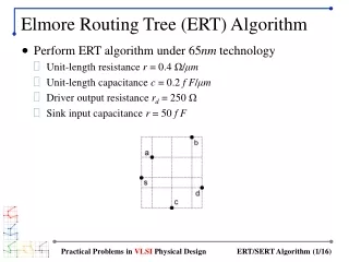
Proposed Algorithm - Example n0 SLIP 2008, Newcastle
Proposed Algorithm - Example n0 SLIP 2008, Newcastle
Proposed Algorithm - Example n0 SLIP 2008, Newcastle
Proposed Algorithm - Example n0 SLIP 2008, Newcastle
Proposed Algorithm - Example n0 SLIP 2008, Newcastle
Proposed Algorithm - Example n0 SLIP 2008, Newcastle
Outline • Y-Routing and Y-Routing Trees • Fidelity of Delay Estimators • Some Previous works • Motivation of our work • Construction of Elmore-based Y-Routing tree • Fidelity and Rank Correlation • Experimental Results • Conclusions SLIP 2008, Newcastle
Rank Correlation for Fidelity Does fidelity computation have anything to do with rank correlation? Should fidelity base on discrimination of ALL candidate solutions or only the good solutions? How would the tie cases be handled? Should fidelity be dimensionless? SLIP 2008, Newcastle
Spearman’s Rank Correlation • Two variables x and y • n pairs of observations on x and y are ordered in magnitude • Define rank of ordered observation xj as rank(xj) = j • Spearman’s Rank Correlation is R R = 1 - 6i=1ndi2/(n(n2 – 1)), where di = |rank(xi) – rank(yi)| SLIP 2008, Newcastle
Kendall’s Tau • Two variables x and y • n pairs of observations on x and y are ordered in magnitude • Q = total number of interchanges required for the y values to order them as x values where 0 <Q < n(n-1)/2 • Kendall’s Tau = = 1 – 4Q / n(n-1) = (# concordant pairs - # discordant pairs) / total # of pairs SLIP 2008, Newcastle
Kendall’s Tau: Properties • If the agreement between the two rankings is perfect (i.e., the two • rankings are the same) the coefficient has value 1. • If the disagreement between the two rankings is perfect (i.e., one • ranking is the reverse of the other) the coefficient has value -1. • For all other arrangements the value lies between -1 and 1, and • increasing values imply increasing agreement between the rankings. • If the rankings are completely independent, the coefficient has value • 0 on average. SLIP 2008, Newcastle
Kendall’s Tau: Example Total no. of pairs = 28 No. of concordant pairs = 22 No. of discordant pairs = 6 = 0.57 SLIP 2008, Newcastle
Normalized Delay • δ = absolute delay value for an estimator • µ = the average of all absolute values for the estimator • σ = the standard deviation • Normalized value for delay is given by • δnorm = (δ – μ)/σ • Fidelity of Elmore (Linear) = ratio of the • normalized delay of Elmore (Linear) to Spice SLIP 2008, Newcastle
Outline • Y-Routing and Y-Routing Trees • Fidelity of Delay Estimators • Some Previous works • Motivation of our work • Construction of Elmore-based Y-Routing tree • Fidelity and Rank Correlation • Experimental Results • Conclusions SLIP 2008, Newcastle
Technology Node Parameters B A McCoy K D Boese, A B Kahng and G Robins. Fidelity and near-optimality of elmore-based routing constructions. In Proc. of the IEEE International Conference on Computer Design, pp. 81–84, October 1993 SLIP 2008, Newcastle
Spearman’s Correlation Coefficient SLIP 2008, Newcastle
Kendall’s Tau SLIP 2008, Newcastle
Normalized Delay Ratios SLIP 2008, Newcastle
Outline • Y-Routing and Y-Routing Trees • Fidelity of Delay Estimators • Some Previous works • Motivation of our work • Construction of Elmore-based Y-Routing tree • Fidelity and Rank Correlation • Experimental Results • Conclusions SLIP 2008, Newcastle
What did we achieve? • An efficient algorithm for constructing • Y-routing tree of minimum Elmore delay • Efficient schemes for • Computing fidelities of Elmore and Linear delay estimates against Spice delay values • Confirmation that Fidelity of Elmore is better than fidelity of Linear for unbuffered routing trees SLIP 2008, Newcastle
Possible extensions • Extending the algorithm for X- and M-routing trees and comparing fidelity results for these architectures • Experiments with better delay metrics such as 2-Pole • Experiments with larger nets with variations of several parameters SLIP 2008, Newcastle