Download
1 / 8
80 likes | 82 Views
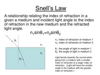
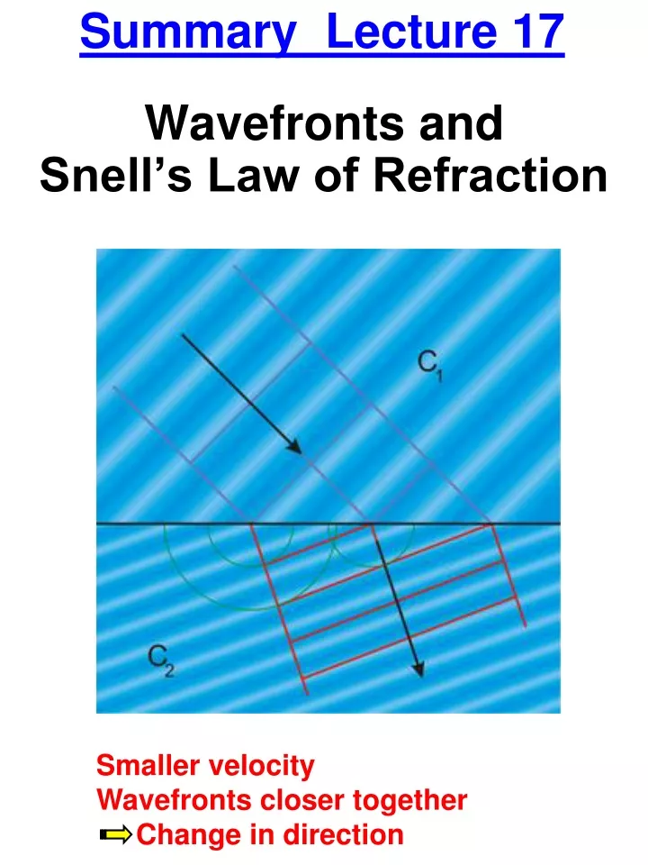
Summary Lecture 17. Wavefronts and Snell’s Law of Refraction. Smaller velocity Wavefronts closer together Change in direction. Refraction. Normal. 1. Medium 1 (n 1 ) Medium 2 (n 2 ). 2. Caused by the difference in the speed of light in medium 1 and 2

E N D
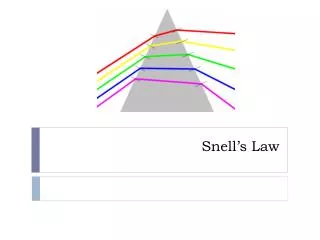
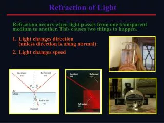
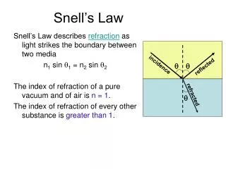
Summary Lecture 17 Wavefronts and Snell’s Law of Refraction Smaller velocity Wavefronts closer together Change in direction
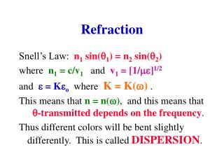
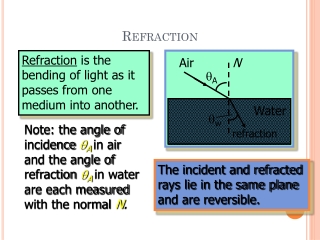
Refraction Normal 1 Medium1(n1) Medium2(n2) 2 Caused by the difference in the speed of light in medium 1 and 2 Index of Refraction n = c/v (nair ~ 1, nWater = 1.33 …) Snell’s Law of Refraction n1 sin 1 = n2 sin 2
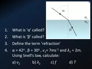
Example A ray of light passes from air (n = 1.0) into glass (n = 1.52) and then into Jell-O. The incident ray makes a 58.0o angle with the normal as it enters the glass and a 36.4o angle with the normal in Jell-O. What is the index of refraction in Jell-O? Glass Jell-O 58.0o 36.4o
Total Internal Reflection going from a medium with large n to a medium with small n “refracted” away from normal n2 1 2 3 4 qc n1 Critical Angle: sin C = n2/n1 > C Total Internal Reflection
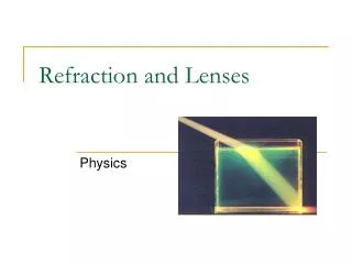
Lenses Lenses refract light in such a way that an image of the light source is formed. Two prisms cause incoming parallel light raysto change direction toward the principal axis Think of a lens as a combination of many prismswith “optimized” shape (spherical instead of flat) With a convex lens parallel light converges to the focal point.
Ray Tracing for Lenses Converging Lenses (convex) Diverging Lenses (concave) • Conventions • Focal Length • f is positive for converging lens • f is negative for diverging lens • Focal Length • f is positive for converging lens • f is negative for diverging lens
Conventions • Focal Length • f is positive for converging lens • f is negative for diverging lens • Object Distance • do is positive if object is to the left of the lens • do is negative if object is to the right of the lens • Image Distance • di is positive if object is to the right of the lens • di is negative if object is to the left of the lens • Object and Image Size • ho, hi are positive if above the principal axis • Image Characterization • Type: the image is real if di is positive • Orientation: the image is upright if hi and ho have the same sign • Size: the image is reduced if | hi | < | ho |
Thin Lens Equation Magnification Equation