Download
1 / 79
870 likes | 1.35k Views
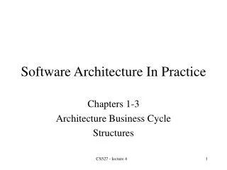
Software Architecture in Practice RiSE’s Seminars Bass’s book :: Chapters 07 Eduardo Cruz Summary Designing the Architecture (Chapter 7) Architecture in the life cycle Designing the Architecture Forming its team structure and its relationship to the architecture Creatign a skeletal system

E N D
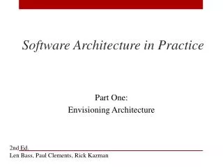
Software Architecturein Practice RiSE’s Seminars Bass’s book :: Chapters 07 Eduardo Cruz
Summary • Designing the Architecture (Chapter 7) • Architecture in the life cycle • Designing the Architecture • Forming its team structure and its relationship to the architecture • Creatign a skeletal system • Evolutionary Delivery Life Cycle • When Can I begin Designing? • How to identify the architectural drivers? • Attribute-Driven Design
Evolutionary Delivery Life Cycle Software Concept Deliver Final Version Preliminary Requirements Analysis Design of Architecture and System Core Develop a Version Deliver the Version Incorporate Customer Feedback Elicit Customer Feedback
Designing the Architecture :: Chapter 7 Evolutionary Delivery Life Cycle • Goal • To get user and customer feedback • Microsoft strategy • Skeletal system • Early • Low-fidelity • Updates
Designing the Architecture :: Chapter 7 When Can I begin Designing? • Architecture shaped by: • Functionality • Quality • Business requirements • Examples • Avionic system • Availability, Performance, Security... • COMPGOV • Availability, Performance, Security... Architectural drivers
Designing the Architecture :: Chapter 7 How to identify the architectural drivers? • To priorize business goals{few} • To put these business goals into qualityscenarios or use cases • Scenary’s template • To choose the most importants • Impact on the architecture
Availability Modifiability Performance Security Testability Usability Designing the Architecture :: Chapter 7 Quality attribute parts ARTIFACT STIMULUS RESPONSE RESPONSE MEASURE SOURCE OF STIMULUS ENVIRONMENT
Designing the Architecture :: Chapter 7 Attribute-Driven Design • Approach to define a software architecture that bases the decomposition process on the quality attributes the software has to fulfill • Recursive decomposition process • Use • Tatics • Architectural Patterns • Systematic approach
Designing the Architecture :: Chapter 7 Attribute-Driven Design (cont.) • To satisfy quality attributes and functional requirements • RUP’s extension • High-level design • Detailed design and implementation • ADD • Detailed {high-level} + Rational • Input • Functional requirements (expressed as use cases) • Constraints • Quality attributes scenarios
ADD Steps (p. 157) • Choose the module to decompose • Module: the system • Inputs: requirements, quality attributes, constraints • Quality attributes scenarios • Refine the module • Choose the architectural drivers from the set of concrete quality scenarios and functional requirements • Choose an architectural pattern that satisfies the architectural drivers • Instantiate modules and allocate functionality from the use cases • Define interfaces of the child modules • Verify and refine use cases and quality scenaries • Repeat the steps above for every module that needs further decomposition
ADD Steps • Choose the module to decompose • System • Subsystem • Submodules • Choose the architectural drivers • Combination of functional and quality requirements that “shape” the architecture or the particular module under considerations • It is not always a top-down process • Prototype • Decomposition criterias • Based on architectural drivers • Requirements priorization Subsystem System Subsystem
ADD Steps (cont.) • Choose an Architectural Pattern • Goal: To establish an overall architectural pattern consisting of module types • Quality attributes -> Tatics -> Patterns • Instantiate Modules and Allocate Functionality using Multiple Views • Instantiate module • Use of responsability • Allocate functionality • Based on Use cases • Represent the architecture with views (flexibility) • Iterative process • One view is normally sufficient • Module decomposition • Concurrency • Deployment • Others aspects can be used
ADD Steps (cont.) • Define Interfaces of the Child Modules • Documentation aspects • Verify and Refine Use cases and Quality Scenarios as Constraints for the Child Modules • Functional requirements • Requirements + use cases -> module • Constraints • The decomposition satisfies the constraint • The constraint is satisfied by a single child module • The constraint is satisfied by multiple child module
ADD Steps (cont.) • Quality scenarios • A quality scenario may be completely satisfied by the decomposition without any additional impact • A quality scenario may be satisfied by the current decomposition with constraints on child modules • The decomposition may be neutral with respect to a quality scenario • A quality scenario may not be satisfiable with the current decompostion • Result • Child module • Responsability • Use cases • Interfaces • Quality scenario • Constraints
References • L. Bass, P. C. Clements, R. Kazman. Software Architecture in Practice. Second Edition, Addison-Wesley, 2003.
Functionality-based architecture design {Design & Use of Software Architectures} RiSE’s Seminars Jan Bosch’s book :: Chapter 4 Vinicius Cardoso Garcia
Summary • Introduction • Defining the system context • Identifying the archetypes • Decomposing the architecture into components • Describing system instantiations • Illustrating functionality-based architecture design • Fire-alarm system context • Summary
Introduction • Architectural design is the process of converting a set of requirements into a software architecture • Functionality-based architectural design • Focus on explicit evaluation of and for quality requirements • Does not mean that the functional requirements are irrelevant • Design phase consists of four main steps • Determining the context of the system • Identification of archetypes • Decomposing system into components • Description system instances using the archetypes and the system interfaces
Starting from the functional requirements does not preclude the optimization of quality requirements • An objective and repeatable architectural design method must be organized • Unlikely that architectural design process does not requireiterations to optimize the architecture • An architecture based primarily on functional requirements is more general • It is unlikely that a SA which fulfils a particular set of quality requirements will be applicable in a domain with different FR
Defining the system context • “No objects is an island” (Beck and Cunningham, 1989) -> software systems in general • The role of the software architect is to convert the requirements of the stakeholder concerning the external visible properties of the system into a software architecture • Facilitates the fulfillment of these requirements • The externally visible behavior is present at the interfaces to its context • Explicitly defining the system in terms of the functionality and quality required on its interfaces is an important starting point
Higher-level systems Defining the system context Used by uses uses System Peer-level systems • Additional reason for explicitly defining the system context and boundaries • Is a natural tendency to include more and more aspects during design • When this effort is spent on SA design -> take time • When there is no extreme time pressure, software architects try to extend the domain of he design • Improve the applicability and allow for likely future requirements • That extensions increase the design and development cost Depends on Lower-level systems
Defining the system context • Define the interfaces of the system to external entities. • These entities may be located at a lower level, a higher level or at the same level; • Associate functional and quality requirements with each interface. • Both operational and development quality requirements can be associated with interfaces; • In the case of software product line, the variability in the interfaces supported by the various products in the product line should be explicitly identified and specified. • The cost and resource efficiency of low-end products should not be sacrificed for the requirements of high-end products.
Identifying the archetypes • Identify and define the core abstractions based on which the system is structured -> archetypes • These entities form the most stable part of the system and are generally very stable and only changed in very limited ways. • Large systems often can be described in terms of a small number of archetypes • The identification is largely dependent on the creativeinsight and experience of the architect (or architects) • The primary starting point is a good understanding of the domains • It is possible to recognize recurring patterns whiting the system at various places -> candidate archetypes! • The candidate archetypes are recorded and form a set • The set is analyzed to select the most appropriate archetypes
Identifying the archetypes • The identification of architectural entities is related to domain analysis methods (Prieto-Diaz and Arango, 1991) • Archetypes can be modeled as domain objects • After analyzing the various domain entities, abstracts the most relevant properties and models them as architectural entities • The iteration between them are defined in more detail • ADLs -> architectures are described in terms of components and connectors
Identifying the archetypes • To conclude: • Identification of candidate archetypes; • The selection of a small and stable set of archetypes from the candidates. This may require the exclusion of candidates, but especially the merging of candidates is rather common; • The identification and selection of relations between archetypes.
Decomposing the architecture into components • Archetypes do not represent the architectural structure of the system • They are generally instantiated in several places in the system in several concrete forms • The next step is to define the structure of the software architecture • decomposition into components and relation between these components • This decomposition does note need to be single level • Incorporate two or more recursive levels • Several approaches can be used to identify and select components
Decomposing the architecture into components • Interfaces: Each of the system interfaces should be connected to a component. One possible approach is by associating a component with each interface; • Domains: A second source for components is to associate domains covered by the system. Two types of domains: • application domains - problem intends to address • computer science domains - areas associated with the solution used to solve the problem • Abstraction layers: horizontal layers that implement relevant functionality and simplify the specification of problem-domain functionality at higher levels. Are identified while interacting over the component selection of the system.
Decomposing the architecture into components • Domain entities: The decomposition defined by the domain experts provides a highly valuable input to the identification and selection of components of the system, and software architects are often tempted to select these components right away. • Archetype instantiations: Even the identified archetypes may provide valuable input to selection components. The archetypes are defined based on the identification of recurring patterns throughout the system. These archetype initiations may represent useful components. • Functional x Entity-based decomposition • Functional is concerned with the functions that he system supposed to provide – C, Pascal • The primary concepts that can be identified in the systems – C++, Java, C#
Decomposing the architecture into components Problem domain • Problem-domain x Solution-domain • Both domains can be decomposed according to the main functions and entities in the domain Control theory architecture Compiler architecture Functionality Entity 3-tier architecture Graphical User-interface architecture • To identifying relation on the origin on which component is defined, a second approach is to “script” scenarios for the architecture. • Following a logical sequence of execution in the architecture helps to identify what components need to be able to communicate with each other Solution domain
Decomposing the architecture into components • To summarize... • Identification and specification of components • We have examined the possible sources for the identification of components, including the system interfaces, domains, abstraction layers, domain entities and archetype instantiation. • Identification and specification of relations • Once the components have been identified, the relations between them need to be identified. We have presented some guidelines and hints, based on the origin of the component.
Describing system instantiations • Design is typically an iterative process • integrating activities addressing the overall system • focusing activities on addressing parts of the system that require particular attention • The components of the software architecture are recursively decomposed into lower-level components; • Each component is either populated with instantiated archetypes • fulfill the functionality required from the system or is represented by an individual instantiated archetype; • The generic relations between the archetypes are instantiated for the instantiated archetypes • verification of the match between abstractions and the concrete system decomposition is performed; • Sufficient variability of product-line architectures is verified by the definition of multiple system instantiations, representing different products.
Fire-alarm systems • Defining the context • Is a relatively autonomous system, but it does not provide a number of interfaces to its context • The first issue: whether the mechanical and hardware parts of the detectors and alarm devices are part of the system or not • Those parts to be external -> the interfaces exists between the software and the physical detectors and alarm devices • Second issue: whether the communication of the system is part of the system -> high distributed
operator Building Automation systems Fire-alarm systems - Interfaces interface interface Fire-alarm system interface interface Detector Output
Identifying the archetypes • Point: high-level abstraction concerning fire-alarm domain functionality. It is the abstraction of the two subsequent archetypes; • Detector: captures the core functionality of the fire-detection equipment, including smoke and temperature sensors; • Output: contains generic output functionality, including traditional alarms; • Control unit: connected to a network and can communicate.
Relations between the F-A archetypes Control Unit Point Communicates with Detector Output
Section Section Section Decomposing the architecture into components Communication Physical points • Physical point is an instantiation of the point archetype, whereas the communication component is typically a component based on a solution domain; • Section component is a domain entity in the system, it represents a controller and the physical points is monitored by it; • Also represents a geographic area where the physical points are responsible • That architecture employs an entity-based decomposing and the entities are taken from the solution domain
Describing the system instantiations Small fire-alarm system instantiation Smoke detector Smoke detector Sound alarm Smoke detector Control unit User interface Smoke detector Smoke detector
Two building fire-alarm system instantiation Describing the system instantiations point Control Unit Operator Interface Control Unit Control Unit point point Control Unit point Control Unit point Control Unit Control Unit point point Control Unit point
Summary • The method has a focus on the explicit evaluation of an d design for quality requirements, but that does not mean that the functional requirements are irrelevant. • Before one can start to optimize an architecture for quality requirements, the first step must be to design an initial version of the architecture based on the functional requirements.
References • Bosch, J. Design & Use of Software Architectures, 1st edition ed: Addison-Wesley Professional, 2000. • Prieto-Díaz, R. and Arango, G. Domain Analysis and Software Systems Modeling. IEEE Computer Society Press, 1991.
Software Architecturein Practice RiSE’s Seminars Bass’s et al. Book :: Chapter 12 Fred Durão e Ednaldo Dilorenzo
Summary • The CBAM (Chapter 12) • Concepts • Decision Making Context • The Basis for the CBAM • Calculating ROI • The importance of Cost Modeling • Implementing CBAM • Case Study: The NASA ECS Project
The CBAM – A Quantitative Approach to Architecture Design Decision Making
The CBAM :: Chapter 12 Concepts • The biggest tradeoffs in large, complex systems usually have to do with economics. • How should an organization invest its resources in a manner that will maximize its gains and minimize its risk? • “…perhaps more important than costs, are the benefits than an architecture decision may bring to an organization.” • CBAM provides an assessment of the technical and economic issues and architectural decisions
The CBAM :: Chapter 12 Decision-Making Context • When ATAM is applied to a software system, we have as a result a set of artefacts • a set of architectural views; • a set of stakeholders goals; a set of risks; • a set of tradeoffs points and more… • The ATAM uncovers the architectural decisions, links the to business goals and quality attribute response measures. • The CBAM does not make decisions for the stakeholders. It simply aids in the elicitation and documentation of the costs and benefits (based on ATAM results). • The CBAM can aid the stakeholders in choosing architectural strategies based on their return on investment return on investment (ROI) – the ratio of benefit to cost.
The CBAM :: Chapter 12 The Basis for the CBAM • Variations of Scenarios • a way to concretely express and represent specific quality attributes • Utility-Response Curves • Every stimulus-response value pair in a scenario provides some utility to the stakeholders, and the utility of different possible values for the response can be compared. • Priorities of Scenarios • Different scenarios within a given system have different levels of importance to the stakeholders and hence different utilities. • To characterize the relative importance of each scenario, a weigh is assigned through a two-step voting exercise.
The CBAM :: Chapter 12 The Basis for the CBAM {2} • Architectural Strategies • In order to move from the current utility attribute response level to the desired or even best-case level. • Side Effects • Impact of the changes
The CBAM :: Chapter 12 Calculating ROI • R (ROI) = B (Benefit) / C (Cost) • This can be used to determine the optimal order for implementation the various strategies.
The CBAM :: Chapter 12 The importance of Cost Modeling • “How do I convince my boss to investing in availability ?” • Maintain high availability requires a high level of redundancy with a rollover capability • This takes time an personnel • Personnel cost money as do purchasing highly available software and adapting it for particular needs • Cost models are imperfect for a wide variety of reasons, but they are the only tools available to constrain requirements.