Download
1 / 47
500 likes | 1.47k Views
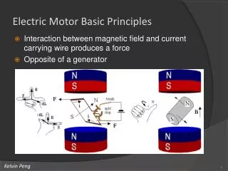
Basics of a Electric Motor. A Two Pole DC Motor. A Four Pole DC Motor. Operating Principle of a DC Machine. 90 0. 90 0. 90 0. Fleming’s Left Hand Rule Or Motor Rule. FORE FINGER = MAGNETIC FIELD. THUMB = MOTION. MIDDLE FINGER= CURRENT. FORCE = B I A l. Fleming’s Right Hand Rule Or

E N D
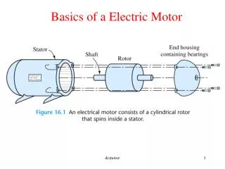
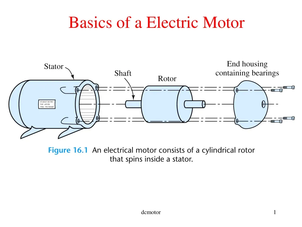
Basics of a Electric Motor dcmotor
A Two Pole DC Motor dcmotor
A Four Pole DC Motor dcmotor
900 900 900 Fleming’s Left Hand Rule Or Motor Rule FOREFINGER = MAGNETIC FIELD THUMB = MOTION MIDDLE FINGER= CURRENT FORCE = B IAl dcmotor
Fleming’s Right Hand Rule Or Generator Rule FOREFINGER = MAGNETIC FIELD 900 900 THUMB = MOTION 900 MIDDLE FINGER = INDUCED VOLTAGE VOLTAGE = B lu dcmotor
Action of a Commutator dcmotor
Armature of a DC Motor dcmotor
Armature Winding in a DC Machine dcmotor
Lap Winding of a DC Machine • Used in high current • low voltage circuits • Number of parallel paths • equals number of brushes • or poles dcmotor
Wave Winding of a DC Machine • Used in high voltage • low current circuits • Number of parallel paths • always equals 2 dcmotor
Summary of a DC Machine • Basically consists of • An electromagnetic or permanent magnetic structure called • field which is static • An Armature which rotates • The Field produces a magnetic medium • The Armature produces voltage and torque under the action • of the magnetic field dcmotor
Deriving the induced voltage in a DC Machine dcmotor
Deriving the electromagnetic torque in a DC Machine dcmotor
Voltage and Torque developed in a DC Machine • Induced EMF, Ea = Kam (volts) • Developed Torque, Tdev = KaIa(Newton-meter or Nm) • where m is the speed of the armature in rad/sec., is the flux per pole in weber (Wb) • Ia is theArmature current • Ka is the machine constant dcmotor
Interaction of Prime-mover DC Generator and Load Tdev Ia + + m Prime-mover (Turbine) VL Ea DC Generator Load - Tpm - Ea is Generated voltage VL is Load voltage Tpm is the Torque generated by Prime Mover Tdev is the opposing generator torque dcmotor
Interaction of the DC Motor and Mechanical Load Ia Tload + Mechanical Load (Pump, Compressor) + VT m DC Motor Ea - - - Tdev Ea is Back EMF VT is Applied voltage Tdev is the Torque developed by DC Motor Tload is the opposing load torque dcmotor
Power Developed in a DC Machine Neglecting Losses, • Input mechanical power to dc generator • = Tdev m= KaIam =Ea Ia • = Output electric power to load • Input electrical power to dc motor • = Ea Ia=Ka m Ia = Tdev m • = Output mechanical power to load dcmotor
Equivalence of motor and generator • In every generator there is a motor (Tdev opposes Tpm) • In every motor there is a generator (Ea opposes VT) dcmotor
Example of winding specific motor and generator Worked out on greenboard dcmotor
Magnetization Curve • Flux is a non-linear • function of field current and • hence Eais a non-linear • function of field current • For a given value of flux Ea • is directly proportional to • m dcmotor
Separately Excited DC Machine RA + Armature Vf - Field Coil dcmotor
Shunt Excited DC Machine Shunt Field Coil Armature RA dcmotor
Series Excited DC Machine RA Armature Series Field Coil dcmotor
Compound Excited DC Machine Series Field Coil Shunt Field Coil Armature RA • If the shunt and series field aid each other it is called a cumulatively • excited machine • If the shunt and series field oppose each other it is called a differentially • excited machine dcmotor
Armature Reaction(AR) • AR is the magnetic field produced by the • armature current • AR aids the main flux in one half of the • pole and opposes the main flux in the • other half of the pole • However due to saturation of the pole • faces the net effect of AR is demagnetizing dcmotor
Effects of Armature Reaction • The magnetic axis of the AR is 900 electrical (cross) out-of-phase with the main flux. This causes commutation problems as zero of the flux axis is changed from the interpolar position. dcmotor
Minimizing Armature Reaction • Since AR reduces main flux, voltage in generators and torque in motors reduces with it. This is particularly objectionable in steel rolling mills that require sudden torque increase. • Compensating windings put on pole • faces can effectively negate the effect • of AR. These windings are connected • in series with armature winding. dcmotor
Minimizing commutation problems • Smooth transfer of current during • commutation is hampered by • a) coil inductance and • b) voltage due to AR flux in the interpolar axis. This voltage is called reactance voltage. • Can be minimized using interpoles. They • produce an opposing field that cancels out the AR in the interpolar region. Thus this winding is also connected in series with the armature winding. • Note: The UVic lab motors have interpoles in them. This should be connected in series with the armature winding for experiments. dcmotor
Question: Can interpoles be replaced by compensating windings and vice-versa? Why or why not? dcmotor
Separately Excited DC Generator Ra Rf If + + RL Vt + Vf Armature Ea Field Coil - - - Ia Field equation: Vf=RfIf Armature equation: Vt=Ea-IaRa Vt=IaRL, Ea=Kam dcmotor
Shunt Generators If Ia – If Ia + Ea + Shunt Field Coil Armature - RL Vt Field coil has Rfw : Implicit field resistance Ra - Rfc Armature equation: Vt=Ea-Ia Ra Vt=(Ia – If) RL, Ea=Kam Field equation: Vt=Rf If Rf=Rfw+Rfc dcmotor
Example on shunt generators’ buildup • For proper voltage build-up the • following are required: • Residual magnetism • Field MMF should aid residual magnetism • Field circuit resistance should be less than critical • field circuit resistance dcmotor
Separately Excited DC Motor Ra Rf If + + + Vf Armature Ea Vt Field Coil - - - Ia Field equation: Vf=RfIf Armature equation: Ea=Vt-IaRa Ea=Kam dcmotor
Separately Excited DC Motor Torque-speed Characteristics RA + Armature + Vf Mechanical Load - - Field Coil m T dcmotor
Separately excited DC Motor-Example I A dc motor has Ra =2 , Ia=5 A, Ea = 220V, Nm = 1200 rpm. Determine i) voltage applied to the armature, developed torque, developed power . ii) Repeat with Nm = 1500 rpm. Assume same Ia. Solution on Greenboard dcmotor
Speed Control of Separately Excited DC Motor(2) • By Controlling Terminal Voltage Vt and keeping If or • constant at rated value .This method of speed control is applicable • for speeds below rated or base speed. T1<T2< T3 V1<V2<V3 m T1 T2 T3 V3 V2 VT V1 dcmotor
Speed Control of Separately Excited DC Motor • By Controlling(reducing)Field Current If or and keeping • Vt at rated value. This method of speed control is applicable • for speeds above rated speed. 1> 2> 3 T1<T2< T3 m 1 T1 2 T2 T3 3 dcmotor
Regions of operation of a Separately Excited DC Motor dcmotor
Separately excited dc motor –Example 2 A separately excited dc motor with negligible armature resistance operates at 1800 rpm under no-load with Vt =240V(rated voltage). The rated speed of the motor is 1750 rpm. i) Determine Vt if the motor has to operate at 1200 rpm under no-load. ii) Determine (flux/pole) if the motor has to operate at 2400 rpm under no-load; given that K = 400/. iii) Determine the rated flux per pole of the machine. Solution on Greenboard dcmotor
Series Excited DC Motor Torque-Speed Characteristics Rsr Rae Ra + Armature Series Field Coil - T m dcmotor
Losses in dc machines dcmotor
Losses in dc machines-shunt motor example If Ia – If Ia + + Vt Ea Shunt Field Coil - - Armature Mechanical Load Field coil has Rfw : Implicit field resistance Ra Rfc Armature equation: Vt=Ea+Ia Ra Ea=Kam Field equation: Vt=Rf If Rf=Rfw+Rfc dcmotor