Download
1 / 37
380 likes | 552 Views
QC in a Digital World. John Aldrich PhD FCCPM Department of Radiology Vancouver Coastal Health University of British Columbia. Digital Imaging. Any sufficiently advanced technology is indistinguishable from magic… Arthur C Clarke 1961. Overview . New paradigms Standards

E N D
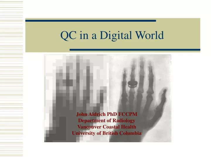
QC in a Digital World John Aldrich PhD FCCPM Department of Radiology Vancouver Coastal Health University of British Columbia
Digital Imaging Any sufficiently advanced technology is indistinguishable from magic… Arthur C Clarke 1961
Overview • New paradigms • Standards • Image acquisition systems • Radiography DR, CR • Fluoroscopy, Angiography DF • CT • US • PACS
New Paradigm In electronic imaging the functional parts of conventional radiology have been separated: • Image Capture • Image Storage • Image Display
Test tool/phantom • Standard imaging parameters/conditions • Scheduled testing (Daily/Weekly) • Defined and objective acceptance/rejection criteria • Patient replaces the phantom • Non-standard imaging parameters/conditions • Frequent testing (every patient) • Ill-defined and subjective acceptance/rejection criteria Imaging QC Principles Proactive QCrather thanReactive QC
First constancy testing Baseline value determination Clinical use period Next constancy testing Data evaluation Within the established criteria PASS FAIL Remedy Quality Control (QC) • Acceptance testing • New equipment • Conformance to manufacture’s specs/criteria • Routine performance evaluations • Specific tests performed at regular intervals • Consistency checks • Evaluate malfunctioning or out-of-spec equipment
Digital System QC Film Developed And Fixed Viewed Display Detector Reading Digital Processing Stored PACS QC of the digital systems is an additional requirement – in addition to the usual x-ray performance tests
Safety Code 20A (1981-2000) Recommended safety procedures for the installation, use and control of x-ray equipment. Mainly concerned with the x-ray output parameters of the equipment Only film processor QC defined Safety Code XX (due 2008) Recommended safety procedures for the installation, use and control of x-ray equipment. Mainly concerned with the x-ray output parameters of the equipment 25% of the Code is concerned with QC of the digital imaging detector systems Health Canada - Quality Control
Digital X-ray Systems • Direct Radiography DR • Formation of image without a secondary read-out device • Computed Radiography CR • Use of storage phosphor plate usually in a cassette-based system • Digital Fluoroscopy/Angiography DF • Image intensifier/video system replaced by digital plate. • Computed Tomography CT • Ultrasound US
DR, CR and DF – Extra QC • Routine QC interval will depend on system – not less than annually • Dose Calibration • Spatial Resolution • Low Contrast • Uniformity • Artifacts • Spatial Linearity
Dose Calibration • Each system should be calibrated according to the manufacturers protocol, as they are all slightly different • General set-up • Arrange for defined dose at surface of cassette at 80 kVp • Expose and read image • Record Exposure Index • The image can also be used to check for uniformity, linearity and artifacts
Image Quality • All CR and some DR/DF manufacturers have special Image Quality phantoms and automatic software to analyze image quality
Resolution and Contrast • Any high contrast resolution phantom can be used to provide comparative information • Low contrast resolution is one of the most difficult parameters to measure • There are several phantoms and measurement is subjective, so consistent technique is essential
Digital Radiography QC • Many DR systems require more frequent calibration of the uniformity eg every month • Flat field measurement (uniform copper plate) • Uniformity correction • Noise • Artifacts • Contrast-detail and resolution phantom
Special Requirements for CR QC • In film screen systems the film is changed for every image • With CR the IP is read up to 10,000 times • Almost all plates suffer from wear artifacts • If you are suspicious about an artifact take an image using the same plate and no patient • Make sure there is a QC program to detect wear before you detect it clinically Hammerstrom et al J Digital Imaging 2006 19:226
Observations • Sharp particulates embedded in the felt lining under a plastic clip etched phosphor surface to create density on radiograph • Not enough pressure beside plastic clip to cause 2nd wear mark to effect radiograph
Observations • Yellowing of phosphor • Virox
Observations Scratches Dust
CR QC Recommendations • Quality Control (QC) - perform monthly • Inspection – cassette and IP • Visual • Radiographic • CR Cassette cleaning • CR IP cleaning • Benefits • Fewer image artifacts and repeated exposures • Increased life cycle of cassettes, IPs, and readers • Compliance with vendor warranties
Consistency Checks • Weekly/daily • Simple phantom to test reproducibility • To use if there seems to be a problem
Low contrast circles High contrast mesh Vancouver Phantom • This phantom we have developed for routine constancy QC of digital systems • Field collimation • Standard operating conditions • Resolution • Contrast
In-air calibration of scanner every 24 hours Adjusts sensitivity of all detectors Important to do this – build into schedule. QC in CT - Daily
QC Phantoms • ACR CT Accreditation Phantom (RMI) • Alignment, noise, uniformity, CT number, resolution, MTF, low contrast, image slice width • Scanner QC phantoms • GE: noise, uniformity, resolution, MTF, low contrast • Siemens: noise, uniformity, MTF
US Probe Test Report Cracked/Dead Elements
Ultrasound QC – Clinical • 6 dead elements – right image • Slight shadowing in the middle of the image • Discernable loss of signal amplitude
Optimization of Displays • Clean the surface of the display • With the display OFF look at reflections on the surface of the display such as lamps, windows, white coats and name tags. Reduce these artifacts as much as possible • Display the SMPTE test pattern • Ensure you can see the 5% and 95% grey scales
Radiology Workstation Contrast Aldrich JE et al. J Digital Imaging 2005;18:287-295
181 Calibration of Displays • Software generates grayscale levels • Photometer measures the luminance output at each level and adjusts video card output to obtain a perceptually linear gradation between grayscale levels • Calibrates display to DICOM standard
Primary PACS Displays • Primary reporting workstations should be used in custom-built reporting areas with low reflecting surfaces, ergonomically-designed chairs, recessed pot lighting with dimmer controls and climate control. • Our primary reporting stations are calibrated for luminance and contrast ratio every three months.
Secondary PACS Displays • In contrast, the secondary displays are used under a range of conditions, often with the possibility of distracting reflections and high ambient lighting. • The secondary displays are checked normally only on installation • Calibration factors can often be changed by the user. • Location: • Operating Rooms • Emergency Rooms • 3D Processing workstations • (Offices, wards, home)
The Imaging Chain • Image are used to follow disease processes so it important that the whole digital chain is linear • Linearity should be checked after changes to software/hardware in any component Detector Reading Digital Processing Stored PACS Viewed Display
The Future The only perfect science ishindsight