Download
1 / 43
460 likes | 1.77k Views
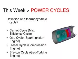
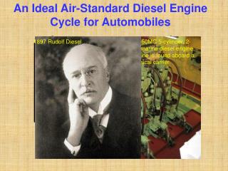
Diesel / Brayton Cycles ASEN 3113 . Diesel Cycle. Invented by Rudolf Christian Karl Diesel in 1893 First engine was powered by powdered coal Achieved a compression ratio of almost 80 Exploded, almost killed Diesel First working engine completed 1894 - generated 13 hp. Diesel Engine.

E N D
Diesel / Brayton Cycles ASEN 3113
Diesel Cycle • Invented by Rudolf Christian Karl Diesel in 1893 • First engine was powered by powdered coal • Achieved a compression ratio of almost 80 • Exploded, almost killed Diesel • First working engine completed 1894 - generated 13 hp
Diesel Engine • Also known as Compression Ignition Engine (CI) • Can this engine “knock”? • Difference from Otto Cycle?
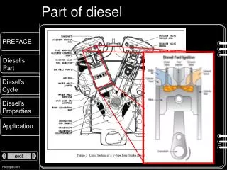
Thermodynamic Cycles for CI engines • In early CI engines the fuel was injected when the piston reached TDC • and thus combustion lasted well into the expansion stroke. • In modern engines the fuel is injected before TDC (about 15o) Fuel injection starts Fuel injection starts Early CI engine Modern CI engine • The combustion process in the early CI engines is best approximated by • a constant pressure heat addition process Diesel Cycle • The combustion process in the modern CI engines is best approximated • by a combination of constant volume and constant pressure Dual Cycle
Early CI Engine Cycle and the Thermodynamic Diesel Cycle Fuel injected at TC A I R Air Combustion Products Actual Cycle Intake Stroke Compression Stroke Power Stroke Exhaust Stroke Qin Qout Air Diesel Cycle BC Compression Process Const pressure heat addition Process Expansion Process Const volume heat rejection Process
Cut-off ratio: Air-Standard Diesel cycle Process a b Isentropic compression Process b c Constant pressure heat addition Process c d Isentropic expansion Process d a Constant volume heat rejection - a=1,b=2,etc…for book
First Law Analysis of Diesel Cycle Equations for processes 12, 41 are the same as those presented for the Otto cycle 23 Constant Pressure Heat Addition now involves heat and work Qin AIR
3 4 Isentropic Expansion AIR note v4=v1 so
Thermal Efficiency For cold air-standard the above reduces to: recall, Note the term in the square bracket is always larger than one so for the same compression ratio, r, the Diesel cycle has a lower thermal efficiency than the Otto cycle So why is a Diesel engine usually more efficient?
Thermal Efficiency Typical CI Engines 15 < r < 20 When rc (= v3/v2)1 the Diesel cycle efficiency approaches the efficiency of the Otto cycle Higher efficiency is obtained by adding less heat per cycle, Qin, run engine at higher speed to get the same power.
The cut-off ratio is not a natural choice for the independent variable a more suitable parameter is the heat input, the two are related by: as Qin 0, rc1 k = 1.3 k = 1.3 - compares performance of engines of the same size
Modern CI Engine Cycle and the Thermodynamic Dual Cycle Fuel injected at 15o before TDC A I R Air Combustion Products Actual Cycle Intake Stroke Compression Stroke Power Stroke Exhaust Stroke Qin Qin Qout Air Dual Cycle TC BC Const volume heat addition Process Compression Process Const pressure heat addition Process Expansion Process Const volume heat rejection Process
Dual Cycle Process 1 2 Isentropic compression Process 2 2.5 Constant volume heat addition Process 2.5 3 Constant pressure heat addition Process 3 4 Isentropic expansion Process 4 1 Constant volume heat rejection Qin 3 2.5 3 Qin 2 2.5 4 2 4 1 Qout 1
Thermal Efficiency Note, the Otto cycle (rc=1) and the Diesel cycle (a=1) are special cases:
The use of the Dual cycle requires information about either: • the fractions of constant volume and constant pressure heat addition • (common assumption is to equally split the heat addition), or • ii) maximum pressure P3. • Transformation of rc and a into more natural variables yields For the same initial conditions P1, V1 and the same compression ratio: For the same initial conditions P1, V1 and the same peak pressure P3 (actual design limitation in engines):
Brayton Cycle • Introduced by George Brayton (an American) in 1872 • Used separate expansion and compression cylinder • Constant Combustion process
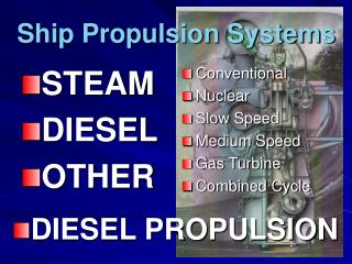
Other applications of Brayton cycle • Power generation - use gas turbines to generate electricity…very efficient • Marine applications in large ships • Automobile racing - late 1960s Indy 500 STP sponsored cars
Brayton Cycle • 1 to 2--isentropic compression • 2 to 3--constant pressure heat addition (replaces combustion process) • 3 to 4--isentropic expansion in the turbine • 4 to 1--constant pressure heat rejection to return air to original state
Brayton cycle analysis • Because the Brayton cycle operates between two constant pressure lines, or isobars, the pressure ratio is important. • The pressure ratio is not a compression ratio. Efficiency: Net work:
Brayton cycle analysis 1 to 2 (isentropic compression in compressor), apply first law **When analyzing the cycle, we know that the compressor work is in (negative). It is standard convention to just drop the negative sign and deal with it later:
Brayton cycle analysis 2 to 3 (constant pressure heat addition - treated as a heat exchanger) 3 to 4 (isentropic expansion in turbine)
Brayton cycle analysis 4 to 1 (constant pressure heat rejection) We know this is heat transfer out of the system and therefore negative. In book, they’ll give it a positive sign and then subtract it when necessary.
Brayton cycle analysis net work: Substituting:
Brayton cycle analysis Thermal efficiency:
Brayton cycle analysis assume cold air conditions and manipulate the efficiency expression:
Brayton cycle analysis Using the isentropic relationships, Define:
Brayton cycle analysis Then we can relate the temperature ratios to the pressure ratio: Plug back into the efficiency expression and simplify:
Brayton cycle analysis An important quantity for Brayton cycles is the Back Work Ratio (BWR).
The Back-Work Ratio is the Fraction of Turbine Work Used to Drive the Compressor
EXAMPLE PROBLEM • The pressure ratio of an air standard Brayton cycle is 4.5 and the inlet conditions to the compressor are 100 kPa and 27C. The turbine is limited to a temperature of 827C and mass flow is 5 kg/s. Determine • a) the thermal efficiency • b) the net power output in kW • c) the BWR • Assume constant specific heats.
Start analysis Let’s get the efficiency: From problem statement, we know rp = 4.5
Net power output: Net Power: Substituting for work terms: Applying constant specific heats:
Need to get T2 and T4 Use isentropic relationships: T1 and T3 are known along with the pressure ratios: T2: T4: Net power is then:
Back Work Ratio Applying constant specific heats:
Brayton Cycle • In theory, as the pressure ratio goes up, the efficiency rises. The limiting factor is frequently the turbine inlet temperature. • The turbine inlet temp is restricted to about 1,700 K or 2,600 F. • Consider a fixed turbine inlet temp., T3
Brayton Cycle • Irreversibilities • Compressor and turbine frictional effects - cause increase in entropy • Also friction causes pressure drops through heat exchangers • Stray heat transfers in components • Increase in entropy has most significance • wc = h2 – h1 for the ideal cycle, which was isentropic • wt = h3 – h4 for the ideal isentropic cycle
Brayton Cycle • In order to deal with irreversibilities, we need to write the values of h2 and h4 as h2,s and h4,s. • Then