Download
1 / 33
330 likes | 621 Views
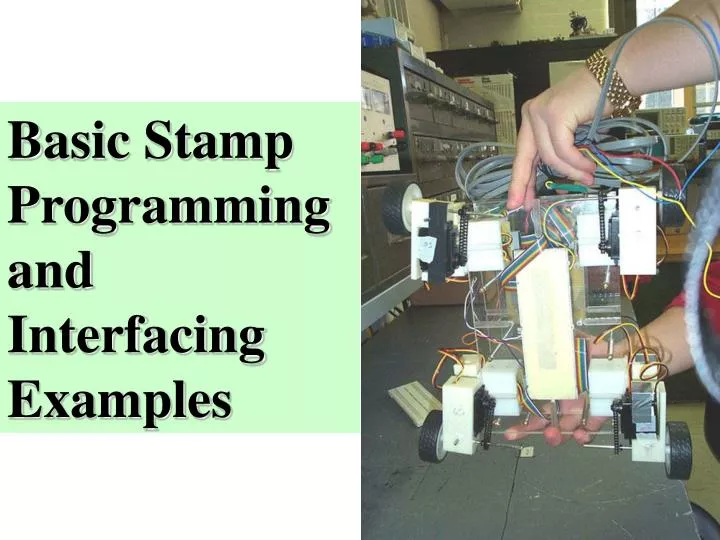
Basic Stamp Programming and Interfacing Examples. BASIC Stamp will be used for illustration. Many pre-defined functions Cost-point: $34-$99 Starter kit for $149. BSII Carrier Board. First LED circuit. Schematic. Experiment #1’ electrical diagram.

E N D
BASIC Stamp will be used for illustration • Many pre-defined functions • Cost-point: $34-$99 • Starter kit for $149
First LED circuit Schematic. Experiment #1’ electrical diagram This is how circuit looks like when you physically build it. The flat side of the LED is closest to the resistor
Example Program 1 for this task output 0 ’make PO an output reblink: ‘ this is where the loop begins out0 = 0 ‘ turn on the LED pause 1000 ‘ wait for 1 second, with the LED on out0 = 1 ‘ now turn off the LED pause 1000 ‘ leave the LED off for 1 second goto reblink ‘ go back, and blink the LED again High school students, attention deficit disorder (ADD), what have been done.
Voltage Flow Diagram LED on. When PO is “low” and current flows, the LED is on. LED off. When PO is “high” there is no current flow
Prototyping or “bread” board Breadboard connections: The horizontal black lines show how the “sockets” are connected underneath the breadboard. This means you don’t have to plug two wires into one socket since thesocket to the right or left is connected. I/O Pin connections are along left power connections are along the top “Vdd” is +5 volts “Vss” is ground
The Language of Basic • Basic programming is notvery hard. • Many of your programs will only be a few lines long. • You should look through the list of commands available to your micro-controller. • There are different flavors of BASIC. • For instance the Basic Stamp uses many macros like RCTIME and SEROUT that are very useful but you may not recognize them if you already know BASIC. • There are also no line numbers.
The Language of Basic • There are a few fundamental programming concepts with which you should familiarize yourself; • 1) Loop • 2) Variables • 3) If Statements. • Case does not matter with the Basic Stamp programming.
Basic Sensing Schemes 1) detect ON/OFF(switches) 2) determine resistance using a resistor/capacitor timing circuit (RCTime) 3) read the frequency of a pulse given off by a device or circuit (PulseIn) 4) use analog to digital converter (A/D) to convert voltage value to number understood by micro-controller
Button • BUTTON pin, downstate, delay, rate, bytevariable, targetstate, address • Debounce button input, perform auto-repeat, and branch to address if button is in target state. • Button circuits may be active-low or active-high. • Pin is a variable/constant (0–15) that specifies the I/O pin to use. • This pin will be made an input. • Downstate is a variable/constant (0 or 1) that specifies which logical state occurs when the button is pressed. • Delay is a variable/constant (0–255) that specifies how long the button must be pressed before auto-repeat starts. • The delay is measured in cycles of the Button routine. • Delay has two special settings: 0 and 255. • If Delay is 0, Button performs no debounce or auto-repeat. • If Delay is 255, Button performs debounce, but no auto- repeat.
Button • Rate is a variable/constant (0–255) that specifies the number of cycles between autorepeats. • The rate is expressed in cycles of the Button routine. • Bytevariable is the workspace for Button. • It must be cleared to 0 before being used by Button for the first time. • Targetstate is a variable/constant (0 or 1) that specifies which state the button should be in for a branch to occur. • (0 = not pressed, 1 = pressed) • Address is a label that specifies where to branch if the button is in the target state.
Two variants of Button Circuits 5V 5V To I/O pin 10k To I/O pin 10k
Useful command RCTIME RCTIME pin, state, resultVariable Count time while pin remains in state — usually to measure the charge/ discharge time of resistor/capacitor (RC) circuit. Pin is a variable/constant (0–15) that specifies the I/O pin to use. This pin will be placed into input mode and left in that state when the instruction finishes. State is a variable or constant (1 or 0) that will end the RCtime period. ResultVariable is a variable in which the time measurement (0 to 65535 in 2µs units) will be stored.
Essentials Comments ‘ this is a comment Declarations foo var byte Value assignments foo = foo + 1 Integer Math Labels Label: Goto, gosub, return Ins and Outs (pins)
RC Time Circuits RCTime Circuits
Variants of Rctime circuits 220 ohm I/O pin C
Variable and Constant Declarations You should try to save memory by using the smallest size variable necessary to hold your values Here are some examples of variable declarations using VAR: ‘ Declare variables. mouse var bit ‘ Value can be 0 or 1. cat var nib ‘ Value in range 0 to 15. dog var byte ‘ Value in range 0 to 255. rhino var word ‘ Value in range 0 to 65535. ‘ Declare constants. cheers con 3
LOOPS • The first thing you should do is make your program into a loop so it is always running. • In basic you make a loop by labeling the top of the the loop and using the GOTO command at the bottom of the loop • MYLABLE: 'This sets the label (note :) • HIGH 2 'Turn pin 2 on. • PAUSE 1000 'Pause for about 1 sec. • LOW 2 'Turn pin 2 of • PAUSE 1000 'Pause for about 1 sec. • GOTO MYLABLE ‘Sends it back up to top of loop • To make a loop you first have to understand labels. • You can label a part of your program just by putting the label name followed by a colon. • The first line in the example set the label MYLABLE. • You can call your labels anything you like. • Anything following the single quote mark is considered a comment, which BASIC ignores. • The lines between the label and the goto are repeated. • The last line sends the program back up to the label MYLABLE and starts the loop over.
Serial and Analog I/O SERIAL SERIN Serial input SEROUT Send data serially (for instance can be used for MIDI output) ANALOG I/O RCTIME Measure an RC charge/discharge time. PULSIN To measure pulse-width of incoming signals; useful for some commercial sensors with built-in A/Ds.
EXAMPLE: Allied ADXL202eb accelerometer set-up • E - common (ground -) • C - Y - to data pins • D - X - to data pins • A - Vdd (+) • scaling resistor, green black brown, 500 Ohm • scaling capacitors .1 uF
Pulsin • PULSIN pin, state, resultVariable • Measure the width of a pulse in 2µs units. • Pin is a variable/constant (0–15) that specifies the I/O pin to use. • This pin will be placed into input modeduring pulse measurement and left in that state after the instruction finishes. • State is a variable or constant (0 or 1) that specifies whether the pulse to be measured begins with a 0-to-1 transition (1) or a 1-to-0 transition (0). • ResultVariable is a variable in which the pulse duration (in 2µs units) will be stored.
Basic Accelerometer Code • E - common (ground -) • C - Y - to data pins • D - X - to data pins • A - Vdd (+)
Basic Accelerometer Code y = yoffset yoff_ok: 'debug "x1 ",DEC x," y1 ",DEC y, cr x=(x-xoffset)/xscale y=(y-yoffset)/yscale if x < 127 then xmax_ok x=127 xmax_ok: if y < 127 then ymax_ok y=127 ymax_ok: debug "x ",DEC x," y ",DEC y, cr goto loop x var word y var word high 0 high 1 yoffset con 0 yscale con 1 xoffset con 0 xscale con 1 loop: pulsin 0,1,x pulsin 1,1,y if x > xoffset then xoff_ok x= xoffset xoff_ok: if y > yoffset then yoff_ok
Stamp MIDI Pin Configuration • MIDI out jack
PBasic Program Control BRANCHING IF...THEN Compare and conditionally branch. BRANCH Branch to address specified by offset. GOTO Branch to address. GOSUB Branch to subroutine at address. GOSUBs may be nested up to four levels deep, and you may have up to 255 GOSUBs in your program. RETURN Return from subroutine. LOOPING FOR...NEXT Establish a FOR-NEXT loop.
MIDI programming /*************************************/ ' Useful variables constants for MIDI controller con 176 number var byte value var byte channel var nib '/*************************************/ controlOut: serout 15, 12, 0, [controller + channel, number, value] return
IF THEN STATEMENTS When you want your Basic Stamp to do something depending on something else then you will want to use the IF statement. Unfortunately the Stamp's IF statements don't work just like most languages where the stuff you want to happen comes in the next line. Instead the IF statement sends the program to label if the condition is met. You can label any part of your program just by putting the label name followed by a colon. The if statement test the statement after the if, and when that is true your program jumps to the label specified. INPUT 3 'make pin3 and input MYLABEL: IF IN3 = 1 THEN FLASH GOTO MYLABEL: FLASH: HIGH 5 PAUSE 1000 LOW 5 PAUSE 1000 GOTO MYLABEL
DIGITAL I/O • INPUT Make pin an input • OUTPUT Make pin an output. • REVERSE If pin is an output, make it an input. If pin is an input, make it an output. • LOW Make pin output low. • HIGH Make pin output high. • TOGGLE Make pin an output and toggle state. • PULSIN Measure an input pulse (resolution of 2 µs). PULSOUT Output a timed pulse by inverting a pin for some time (resolution of 2 µs). • BUTTON De-bounce button, perform auto-repeat, and branch to address if button is in target state. • SHIFTIN Shift bits in from parallel-to-serial shift register. • SHIFTOUT Shift bits out to serial-to-parallel shift register. • COUNT Count cycles on a pin for a given amount of time (0 - 125 kHz, assuming a 50/50 duty cycle). • XOUT Generate X-10 powerline control codes. For use with TW523 or TW513 powerline interface module.
Other PBasic Statements • SOUND • FREQOUT Generate one or two sinewaves of specified frequencies (each from 0 - 32767 hz.). • DTMFOUT Generate DTMF telephone tones. • EEPROM ACCESS • DATA Store data in EEPROM before downloading PBASIC program. • READ Read EEPROM byte into variable. • WRITE Write byte into EEPROM. • TIME • PAUSE Pause execution for 0–65535 milliseconds. • POWER CONTROL • NAP Nap for a short period. Power consumption is reduced. • SLEEP Sleep for 1-65535 seconds. • END Sleep until the power cycles or the PC connects. • PROGRAM DEBUGGING • DEBUG Send variables to PC for viewing.
Where to find more? BASIC Stamp MP-Lab Programmer & chips C-compiler http://www.parallaxinc.com http://www.microchip.com http://www.digikey.com http://www.ccsinfo.com http://www.umich.edu/~rodemer rodemer@umich.edu Computers in lab, documentation in lab
Problems to solve from previous classes 1. Analyze our Basic Stamps programs for movement of hexapods and wheeled robots (they are available from lab assistant) 2. Write their small modifications and analyze changes in behavior of the respective robots. 3. Write Basic Stamp programs for the following robots: head, arm, mobile wheeled robot for soccer, walker (hexapod) for soccer. They should be able to turn right, left, back, and have various “gaits”. 4. Observe that “gaits” are also possible for wheeled robots, video of Japanese dolls from NEC, with their funny way of wheeling in little steps. • How to program such behaviors?
Sources • Curtis Bahn, RPI • J.E. Wampler • Michael Rodemer, University of Michigan, School of Art and Design • Physics and Media Group, MIT • Josh R. Fairley • Dr. Raymond S. Winton • Mike Haney, University of Illinois • Steve Benkovic, Cal State University , Northridgehttp://homepage.mac.com/SBenkovic • s.benkovic@ieee.org • Franklin Alioto, Christine Beltran, Eric Cina, Vince Francisco, Margo Gaitan, Matthew O’Connor, Mike Rasay. • Kenneth Chin and Prang Chim • Dr. Jim OstrowskiBob Miller, Wally Szczesniak, Terry Kientz, • Brett Balogh , Siddharth Deliwala, John Bowen, • Darnel Degand, Kapil Kedia, • Adrian Fox, Christopher Li,