Download
1 / 73
730 likes | 939 Views
5.1 Introduction and services 5.2 Error detection and correction 5.3Multiple access protocols 5.4 Link-layer Addressing 5.5 Ethernet. 5.6 Link-layer switches 5.9 A day in the life of a web request. Link Layer. Some terminology: hosts and routers are nodes

E N D
5.1 Introduction and services 5.2 Error detection and correction 5.3Multiple access protocols 5.4 Link-layer Addressing 5.5 Ethernet 5.6 Link-layer switches 5.9 A day in the life of a web request Link Layer 5: DataLink Layer
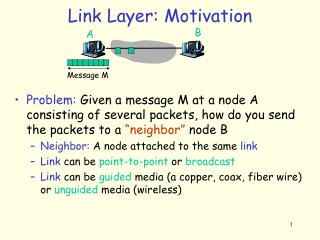
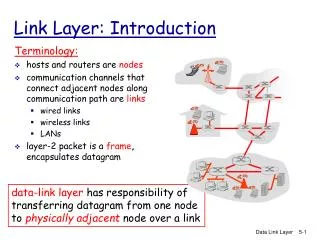
Some terminology: hosts and routers are nodes communication channels that connect adjacent nodes along communication path are links: wired links, wireless links Point-to-point links, multi-access (or broadcast) links layer-2 packet is a frame,encapsulates datagram Link Layer: Introduction data-link layer has responsibility of transferring datagram from one node to adjacent node over a link 5: DataLink Layer
datagram transferred by different link protocols over different links: e.g., Ethernet on first link, frame relay on intermediate links, 802.11 on last link each link protocol provides different services e.g., may or may not provide rdt over link Link layer: context 5: DataLink Layer
network link physical link physical M M M Ht M Hn Hn Hn Hn Ht Ht Ht Ht M M M M Ht Ht Hn Hl Hl Hl Hn Hn Hn Ht Ht Ht M M M source Encapsulation message application transport network link physical segment datagram frame switch destination application transport network link physical router Introduction
Link Layer Services • framing: encapsulate datagram into frame, adding header, trailer • link access: • channel access if shared medium • “MAC” addresses used in frame headers to identify source, dest • different from IP address! • reliable delivery between adjacent nodes • we learned how to do this already (chapter 3)! • seldom used on low bit-error link (fiber, some twisted pair) • wireless links: high error rates • Q: why both link-level and end-end reliability? 5: DataLink Layer
Link Layer Services (more) • flow control: • pacing between adjacent sending and receiving nodes • error detection: • errors caused by signal attenuation, noise. • receiver detects presence of errors: • signals sender for retransmission or drops frame • error correction: • receiver identifies and corrects bit error(s) without resorting to retransmission 5: DataLink Layer
in each and every host link layer implemented in “adaptor” (aka network interface card NIC) Ethernet card, PCMCI card, 802.11 card implements link, physical layer attaches into host’s system buses combination of hardware, software, firmware application transport network link link physical Where is the link layer implemented? host schematic cpu memory host bus (e.g., PCI) controller physical transmission network adapter card 5: DataLink Layer
sending side: encapsulates datagram in frame adds error checking bits, rdt, flow control, etc. receiving side looks for errors, rdt, flow control, etc extracts datagram, passes to upper layer at receiving side Adaptors Communicating datagram datagram controller controller receiving host sending host datagram frame 5: DataLink Layer
5.1 Introduction and services 5.2 Error detection and correction 5.3Multiple access protocols 5.4 Link-layer Addressing 5.5 Ethernet 5.6 Link-layer switches 5.9 A day in the life of a web request Link Layer 5: DataLink Layer
Parity Checking Two Dimensional Bit Parity: Detect and correct single bit errors Single Bit Parity: Detect single bit errors 0 0 5: DataLink Layer
Sender: treat segment contents as sequence of 16-bit integers checksum: addition (1’s complement sum) of segment contents sender puts checksum value into UDP checksum field Receiver: compute checksum of received segment check if computed checksum equals checksum field value: NO - error detected YES - no error detected. But maybe errors nonetheless? Internet checksum (review) Goal: detect “errors” (e.g., flipped bits) in transmitted packet (note: used at transport layer only) 5: DataLink Layer
Checksumming: Cyclic Redundancy Check • view data bits, D, as a binary number (actually, a polynomial with binary coefficients) • choose r+1 bit pattern (generator), G • goal: choose r CRC bits, R, such that • <D,R> exactly divisible by G (modulo 2) • receiver knows G, divides <D,R> by G. If non-zero remainder: error detected! • can detect all burst errors less than r+1 bits • widely used in practice (Ethernet, 802.11 WiFi, ATM) 5: DataLink Layer
Cyclic Redundancy Check • Modulo 2 arithmetic • addition = subtraction = XOR • Each bit string represents a polynomial. • Example: 10011011 corresponds to • A polynomial, G(x), of degree r is known to both sender and receiver. • Sender appends r bits (called CRC code) to the message so that the resulting polynomial can be divided evenly by G(x). • Receiver checks if the received frame (message together with CRC) is still divisible by G(x). • If not, there are transmission errors in the frame.
Common polynomials for G(x): CRC CRC-8 CRC-10 CRC-12 CRC-16 CRC-CCITT CRC-32 C(x) x8+x2+x1+1 x10+x9+x5+x4+x1+1 x12+x11+x3+x2+x1+1 x16+x15+x2+1 x16+x12+x5+1 x32+x26+x23+x22+x16+x12+x11+x10+x8+x7+x5+x4+x2+x+1
CRC Example 5: DataLink Layer
5.1 Introduction and services 5.2 Error detection and correction 5.3Multiple access protocols 5.4 Link-layer Addressing 5.5 Ethernet 5.6 Link-layer switches 5.9 A day in the life of a web request Link Layer 5: DataLink Layer
Multiple Access Links and Protocols Two types of “links”: • point-to-point • PPP for dial-up access • point-to-point link between Ethernet switch and host • broadcast (shared wire or medium) • old-fashioned Ethernet • upstream HFC (cable network) • 802.11 wireless LAN humans at a cocktail party (shared air, acoustical) shared wire (e.g., cabled Ethernet) shared RF (e.g., 802.11 WiFi) shared RF (satellite) 5: DataLink Layer
Cable Network Architecture: Overview Typically 500 to 5,000 homes cable headend home cable distribution network (simplified) Introduction
Multiple Access protocols • single shared broadcast channel • two or more simultaneous transmissions by nodes: interference • collision if node receives two or more signals at the same time multiple access protocol • distributed algorithm that determines how nodes share channel, i.e., determine when node can transmit • communication about channel sharing must use channel itself! • no out-of-band channel for coordination 5: DataLink Layer
Ideal Multiple Access Protocol Broadcast channel of rate R bps 1. when one node wants to transmit, it can send at the full rate, say R. 2. when M nodes want to transmit, each can send at average rate R/M 3. fully decentralized: • no special node to coordinate transmissions • no synchronization of clocks, slots 4. simple 5: DataLink Layer
MAC Protocols: a taxonomy Three broad classes: • Channel Partitioning • divide channel into smaller “pieces” (time slots, frequency, code) • allocate piece to node for exclusive use • Random Access • channel not divided, allow collisions • “recover” from collisions • “Taking turns” • nodes take turns, but nodes with more to send can take longer turns 5: DataLink Layer
Channel Partitioning MAC protocols: TDMA TDMA: time division multiple access • access to channel in "rounds" • each station gets fixed length slot (length = pkt trans time) in each round • unused slots go idle • example: 6-station LAN, 1,3,4 have pkt, slots 2,5,6 idle 6-slot frame 3 3 4 4 1 1 5: DataLink Layer
Channel Partitioning MAC protocols: FDMA FDMA: frequency division multiple access • channel spectrum divided into frequency bands • each station assigned fixed frequency band • unused transmission time in frequency bands go idle • example: 6-station LAN, 1,3,4 have pkt, frequency bands 2,5,6 idle time frequency bands FDM cable 5: DataLink Layer
Random Access Protocols • When node has packet to send • transmit at full channel data rate R. • no a priori coordination among nodes • two or more transmitting nodes ➜ “collision”, • random access MAC protocol specifies: • when a node can send a frame • how to detect collisions • how to recover from collisions (e.g., via delayed retransmissions) • Examples of random access MAC protocols: • ALOHA • CSMA, CSMA/CD, CSMA/CA 5: DataLink Layer
ALOHA • When a node has a frame to send, send immediately. • Set a timer for a random amount of time. • If an ACK arrives before the timer expires, fine; otherwise, resend the frame. • (Works like stop-and-wait with random timeout interval) 5: DataLink Layer
CSMA (Carrier Sense Multiple Access) CSMA: listen before transmit: • If channel sensed idle: transmit entire frame • If channel sensed busy: defer transmission • human analogy: don’t interrupt others! 5: DataLink Layer
CSMA collisions spatial layout of nodes collisions can still occur: propagation delay means two nodes may not hear each other’s transmission collision: entire packet transmission time wasted 5: DataLink Layer
CSMA/CD (Collision Detection) CSMA/CD: carrier sensing, deferral as in CSMA • collisions detected within short time • colliding transmissions aborted, reducing channel wastage • collision detection: • easy in wired LANs: measure signal strengths; compare transmitted & received signals • difficult in wireless LANs: received signal strength overwhelmed by local transmission strength • human analogy: the polite conversationalist 5: DataLink Layer
CSMA/CD collision detection 5: DataLink Layer
“Taking Turns” MAC protocols channel partitioning MAC protocols: • share channel efficiently and fairly at high load • inefficient at low load: delay in channel access, 1/N bandwidth allocated even if only 1 active node! Random access MAC protocols • efficient at low load: single node can fully utilize channel • high load: collision overhead “taking turns” protocols look for best of both worlds! 5: DataLink Layer
data data poll “Taking Turns” MAC protocols Polling: • master node “invites” slave nodes to transmit in turn • typically used with “dumb” slave devices • concerns: • polling overhead • latency • single point of failure (master) master slaves 5: DataLink Layer
“Taking Turns” MAC protocols Token passing: • control token passed from one node to next sequentially. • token message • concerns: • token overhead • latency • single point of failure (token) T (nothing to send) T data 5: DataLink Layer
Summary of MAC protocols • channel partitioning, by time, frequency or code • Time Division, Frequency Division • random access (dynamic), • ALOHA, CSMA, CSMA/CD • carrier sensing: easy in some technologies (wire), hard in others (wireless) • CSMA/CD used in Ethernet • CSMA/CA used in 802.11 • taking turns • polling from central site, token passing • Bluetooth, FDDI, IBM Token Ring 5: DataLink Layer
5.1 Introduction and services 5.2 Error detection and correction 5.3Multiple access protocols 5.4 Link-Layer Addressing 5.5 Ethernet 5.6 Link-layer switches 5.9 A day in the life of a web request Link Layer 5: DataLink Layer
MAC Addresses and ARP • 32-bit IP address: • network-layer address • used to get datagram to destination IP subnet • MAC (or LAN or physical or Ethernet) address: • function:get frame from one interface to another physically-connected interface (in same network) • 48 bit MAC address • burned in NIC ROM 5: DataLink Layer
LAN Addresses and ARP Each adapter on LAN has unique LAN address Broadcast address = FF-FF-FF-FF-FF-FF 1A-2F-BB-76-09-AD LAN (wired or wireless) = adapter 71-65-F7-2B-08-53 58-23-D7-FA-20-B0 0C-C4-11-6F-E3-98 5: DataLink Layer
LAN Address (more) • MAC address allocation administered by IEEE • manufacturer buys portion of MAC address space (to assure uniqueness) • analogy: (a) MAC address: like Social Security Number (b) IP address: like postal address • MAC flat address ➜ portability • can move LAN card from one LAN to another • IP hierarchical address NOT portable • address depends on IP subnet to which node is attached 5: DataLink Layer
Q: given a node’s IP address, how to determine its MAC address? ARP: Address Resolution Protocol • Each IP node (host, router) on LAN has ARP table • ARP table: IP/MAC address mappings for some LAN nodes < IP address; MAC address; TTL> • TTL (Time To Live): time after which address mapping will be forgotten (typically 20 min) 137.196.7.78 1A-2F-BB-76-09-AD 137.196.7.23 137.196.7.14 LAN 71-65-F7-2B-08-53 ??? 0C-C4-11-6F-E3-98 137.196.7.88 5: DataLink Layer
A wants to send datagram to B, and B’s MAC address not in A’s ARP table. A broadcasts ARP query packet, containing B's IP address dest MAC address = FF-FF-FF-FF-FF-FF all machines on LAN receive ARP query B receives ARP packet, replies to A with its (B's) MAC address frame sent to A’s MAC address (unicast) A caches (saves) IP-to-MAC address pair in its ARP table until information becomes old (times out) ARP is “plug-and-play”: nodes create their ARP tables without intervention from net administrator ARP protocol: Same LAN (network) 5: DataLink Layer
88-B2-2F-54-1A-0F 74-29-9C-E8-FF-55 E6-E9-00-17-BB-4B 222.222.222.221 1A-23-F9-CD-06-9B 111.111.111.111 222.222.222.222 222.222.222.220 111.111.111.110 R 111.111.111.112 49-BD-D2-C7-56-2A CC-49-DE-D0-AB-7D B A Addressing: routing to another LAN walkthrough: send datagram from A to B via R assume A knows B’s IP address • two ARP tables in router R, one for each IP network (LAN) LAN LAN 5: DataLink Layer
88-B2-2F-54-1A-0F 74-29-9C-E8-FF-55 E6-E9-00-17-BB-4B 222.222.222.221 1A-23-F9-CD-06-9B 111.111.111.111 222.222.222.222 222.222.222.220 B A 111.111.111.110 R 111.111.111.112 49-BD-D2-C7-56-2A CC-49-DE-D0-AB-7D This is a really important example – make sure you understand! • A creates IP datagram with source A, destination B • A uses ARP to get R’s MAC address for 111.111.111.110 • A creates link-layer frame with R's MAC address as dest, frame contains A-to-B IP datagram • A’s NIC sends frame • R’s NIC receives frame • R removes IP datagram from Ethernet frame, sees its destined to B • R uses ARP to get B’s MAC address • R creates frame containing A-to-B IP datagram sends to B 5: DataLink Layer
5.1 Introduction and services 5.2 Error detection and correction 5.3Multiple access protocols 5.4 Link-Layer Addressing 5.5 Ethernet 5.6 Link-layer switches 5.9 A day in the life of a web request Link Layer 5: DataLink Layer
Ethernet “dominant” wired LAN technology: • cheap $20 for NIC • first widely used LAN technology • simpler, cheaper than token LANs and ATM • kept up with speed race: 10 Mbps – 10 Gbps Metcalfe’s Ethernet sketch 5: DataLink Layer
Star topology • bus topology popular through mid 90s • all nodes in same collision domain (can collide with each other) • today: star topology prevails • active switch in center • each “spoke” runs a (separate) Ethernet protocol (nodes do not collide with each other) switch bus: coaxial cable star 5: DataLink Layer
Ethernet Frame Structure Sending adapter encapsulates IP datagram (or other network layer protocol packet) in Ethernet frame Preamble: • 7 bytes with pattern 10101010 followed by one byte with pattern 10101011 • used to synchronize receiver & sender clock rates 5: DataLink Layer
Ethernet Frame Structure (more) • Addresses: 6 bytes • if adapter receives frame with matching destination address, or with broadcast address (eg ARP packet), it passes data in frame to network layer protocol • otherwise, adapter discards frame • Type: indicates higher layer protocol (mostly IP but others possible, e.g., Novell IPX, AppleTalk) • CRC: checked at receiver, if error is detected, frame is dropped 5: DataLink Layer
Ethernet: Unreliable, connectionless • connectionless: No handshaking between sending and receiving NICs • Unreliable (best effort): receiving NIC doesn’t send acks or nacks to sending NIC • stream of datagrams passed to network layer can have gaps (missing datagrams) • gaps will be filled if app is using TCP • otherwise, app will see gaps • Ethernet’s MAC protocol: CSMA/CD 5: DataLink Layer
1. NIC receives datagram from network layer, creates frame 2. If NIC senses channel idle, starts frame transmission If NIC senses channel busy, waits until channel idle, then transmits 3. If NIC transmits entire frame without detecting another transmission, NIC is done with frame ! 4. If NIC detects collision while transmitting, aborts and sends jam signal 5. After aborting, NIC enters exponential backoff: after m-th collision, NIC waits K slots of time and then returns to Step 2, where K is a random value in {0, 1, 2, …, 2m-1}. (1 slot = 512 bit-times) Ethernet CSMA/CD algorithm 5: DataLink Layer
Jam Signal: make sure all other transmitters are aware of collision; 48 bits Bit time: .1 microsec for 10 Mbps Ethernet ;for K=1023, wait time is about 50 msec Exponential Backoff: Goal: adapt retransmission attempts to estimated current load heavy load: random wait will be longer first collision: choose K from {0,1}; delay is K· 512 bit transmission times after second collision: choose K from {0,1,2,3}… after ten collisions, choose K from {0,1,2,3,4,…,1023} Ethernet’s CSMA/CD (more) 5: DataLink Layer
application transport network link physical fiber physical layer copper (twister pair) physical layer 802.3 Ethernet Standards: Link & Physical Layers • many different Ethernet standards • common MAC protocol and frame format • different speeds: 2 Mbps, 10 Mbps, 100 Mbps, 1Gbps, 10G bps • different physical layer media: fiber, cable MAC protocol and frame format 100BASE-T2 100BASE-FX 100BASE-TX 100BASE-BX 100BASE-SX 100BASE-T4 5: DataLink Layer