Download
1 / 18
230 likes | 437 Views
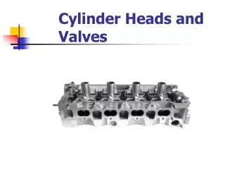
RECONDITIONING CYLINDER HEADS. RK. Chapter 9 Page 209 Classroom Manual Page 207 Lab Manual. CHAPTER OBJECTIVE. RK. Correct valve guide clearance by: Knurling. Reaming to accept oversize valve stems. Installing bronze guide liners. Installing cast iron guide inserts.

E N D
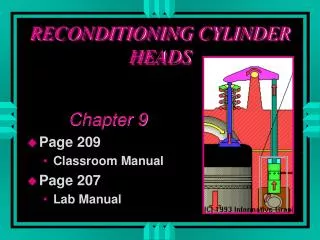
RECONDITIONING CYLINDER HEADS RK Chapter 9 Page 209 Classroom Manual Page 207 Lab Manual
CHAPTER OBJECTIVE RK • Correct valve guide clearance by: • Knurling. • Reaming to accept oversize valve stems. • Installing bronze guide liners. • Installing cast iron guide inserts. • Replace intregal and insert valve seats. • Grind valve seats & correct contact pattern. Page
CHAPTER OBJECTIVE RK • Recondition valve faces & tips. • Identify proper valve face-to-seat contact pattern. • Correct valve stem seal alignment. • Replace worn or damaged pressed-in rocker arm studs with oversize and threaded studs. • Resurface cylinder head sealing surface. Page
CHAPTER OBJECTIVE • Measure & correct valve guide height. • Measure & correct valve spring installed height. • Measure & correct valve stem height.
INTRODUCTION RK • Valve guide repair. • Reconditioning valve guides. • Grinding valves. • Reconditioning valve seats. • Resurfacing cylinder head. Page
RESURFACING THE HEAD RK • Types of resurfacing equipment • Belt sander • Surface grinder • Rotory broach • The amount of material removed, each pass, depends on the type of equipment used. • Resurfacing increases compression ratio. Page
RESURFACING CONCERNS • Spark Knock . • Piston-to-valve interference. • Change in rocker arm geometry. • Change in clearance volume. • Misalignment of the intake manifold. • Inaccurate cam timing on OHC engines. • Surface finish.
SURFACE FINISH • The rougher the surface thehigher the microinch finish.
COMPRESSION RATIO • Combustion chamber volume • Head gasket volume • Deck Height • Cylinder volume
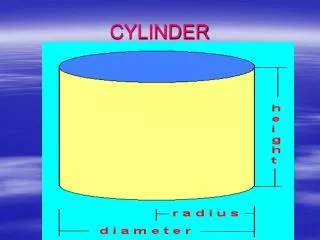
Terms • Radius = diameter /2 • Squared = number multiplied by itself • Pi = 3.1416 • Stroke = Piston movement TDC to BDC
COMBUSTION CHAMBER • Measure combustion chamber in cc’s
HEAD GASKET • Figure head gasket volume • Use formula Pi x radius2 x height • Convert to cc’s, ci x 16.3866 = cc
DECK HEIGHT • Bring piston to TDC • Measure from deck to piston • Figure area Pi x r2 x height
CYLINDER VOLUME • Bore divided by 2 • Pi r2 x stroke
CLEARANCE VOLUME AT TDC • Combustion chamber volume in cc’s • Head gasket volume in cc’s • Deck height volume in cc’s ______ • Total
CLEARANCE VOLUME AT BDC • Combustion chamber volume in cc’s • Head gasket volume in cc’s • Deck height volume in cc’s • Cylinder volume in cc’s ______ • Total
COMPRESSION RATIO • Clearance volume at TDC ________________________ = CR • Clearance volume at BDC