Download
1 / 31
310 likes | 326 Views
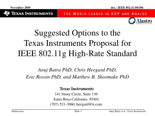
Texas Instruments Proposal for IEEE 802.11g High-Rate Standard. Chris Heegard, PhD, Eric Rossin , PhD , Matthew Shoemake , PhD , Sean Coffey , PhD and Anuj Batra , PhD. Texas Instruments 141 Stony Circle, Suite 130 Santa Rosa California 95401 (707) 521-3060, heegard@ti.com. Outline.

E N D
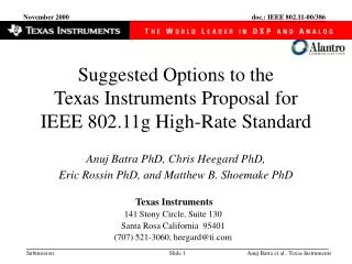
Texas Instruments Proposal for IEEE 802.11g High-Rate Standard Chris Heegard, PhD, Eric Rossin, PhD, Matthew Shoemake , PhD, Sean Coffey , PhD and Anuj Batra , PhD Texas Instruments 141 Stony Circle, Suite 130 Santa Rosa California 95401 (707) 521-3060, heegard@ti.com Chris Heegard, Texas Instruments
Outline • Introduction • Improved utilization of the 2.4 GHz ISM band for wireless Ethernet • The TI/Alantro 22 Mbps solution • How it works • Why it is good • Certification Issues • Processing Gain • Jamming Requirements • The ACX101 Baseband Processor • Summary Chris Heegard, Texas Instruments
Introduction “Double the Data Rate” Wireless Ethernet Chris Heegard, Texas Instruments
T I 25 Others 22 Mbps 20 15 Data Rate, Mbps 11 Mbps 10 5.5 Mbps 5 2 Mbps 0 IEEE 802.11b Noise, Multipath Distortion TI Offers 2x,“Double the Data Rate” • Additive White Gaussian Noise • The TI FEC has a “3db” coding gain advantage • Multipath Distortion • The TI “joint equalizer/decoder” can process much more distortion • The TI “CCK” solution takes advantage of the receiver Chris Heegard, Texas Instruments
Why Increase Performance? • Spectrum is rare and valuable • In order to be efficient it demands the most aggressive practical technical solution • History: as progress is made, more throughput is achieved • Example: Telephone modem technology • Fixed 3 kHz channel • Initial progress: 300 -> 1,200 -> 2,400 -> 4,800 bits/second • Progress was stalled until: • Trellis coding, a form of FEC based on convolutional coding, was developed • Adaptive signal processing was developed • Inspired new wave: 9,600 -> 14,400 -> 28,800 bits/second • The Alantro/TI technology provides the next wave in wireless Ethernet performance Chris Heegard, Texas Instruments
Rate versus SNR 30 Shannon Shannon (r = 11) Barker 1 PER = 10-2 25 Barker 2 CCK 11 PBCC 11 PBCC 22 20 Increase Data Rate (Mbps) 15 Rate 10 5 0 -2 0 2 4 6 8 10 Es/No (dB) Increase Robustness How to Increase Performance? Chris Heegard, Texas Instruments
Packet Binary Convolutional Coding • Combines Binary Convolutional Coding with Codeword Scrambling • For 11 (and 5.5) Mbps • Rate k=1, n = 2 encoder • 64 state • QPSK (BPSK) modulation • Dfree^2/Es = 9/2 = 6.5 dB • For 22 Mbps • Rate k=2, n=3 encoder • 256 state • 8PSK modulation • Dfree^2/Es = 704/98 = 8.6 dB Chris Heegard, Texas Instruments
PBCC Components Chris Heegard, Texas Instruments
BCC Encoder • PBCC-11: • PBCC-22: Chris Heegard, Texas Instruments
100 001 000 111 101 011 010 110 “Symbol Scrambler” s = 0 s = 1 QPSK 01 00 00 10 Mode (1 bit per symbol) 11 10 01 11 (y1,y0) s = 0 s = 1 111 8PSK Mode 000 011 (2 bit per 110 symbol) 100 010 001 (y2,y1,y0) 101 Chris Heegard, Texas Instruments
The “s” Sequence • A length 256 sequence generated from a length 16 sequence • [c0,c1,…,c15] = [0011001110001011] • Periodically extended for >256 Chris Heegard, Texas Instruments
AWGN Performance Chris Heegard, Texas Instruments
Throughput Chris Heegard, Texas Instruments
Throughput (cont.) Chris Heegard, Texas Instruments
Certification Issues PBCC-22 should be certified under existing rules Chris Heegard, Texas Instruments
2 Principle Aspects to Certification • Transmission: The nature of the transmitted signal • What is the power level? • Power Spectrum • Reception: Robustness at the receiver • Depends on the character of the transmitted signal and the sophistication of the receiver • Processing Gain • Measured with respect to a reference • Comparison of Shannon Limits • Interference Rejection • CW Jamming Margin • Narrow Band Gaussian • Noise Chris Heegard, Texas Instruments
The Transmitted Signal Barker 2 CCK 11 PBCC 11 PBCC 22 Chris Heegard, Texas Instruments
The Definition of Spread Spectrum • “I Don’t Know How to Define It, But I Know It When I See It” • This ignores the long history to the science of digital communications • Morse, Nyquist, Shannon, Weiner, Hamming, Elias,… • Although one does need to make logical definitions, similar difficulties exist with other important communications parameters • Signal-to-Noise ratio • Bandwidth • Power Spectrum, etc. • Reasonable Definitions Exist (examples to follow) • Is the definition important? NO • A means to an end --> robust communications Chris Heegard, Texas Instruments
Massey’s Definition • “Towards an Information Theory of Spread- Spectrum Systems” , • Code Division Multiple Access Communications (Eds. S. G. Glisic and P. A. Leppanen) , 1995, James L. Massey. • Defined 2 notions of Bandwidth • “Fourier” or “Nyquest” Bandwidth • Relates to Spectrum Occupancy • “Shannon” Bandwidth • Relates to Signal Space Dimension • Spreading Ratio r • A system is “spread spectrum” if r is large • This definition is mathematically precise and intuitive • This definition argues that high rate (bits/sec/Hz) systems cannot have significant spreading A Theorem Chris Heegard, Texas Instruments
Massey’s Definition Applied to Wireless Ethernet Chris Heegard, Texas Instruments
Data: Symbols: Other Notions of Signal “Spreading” • Uncoded Modulation: • Break data stream into small pieces • map onto independent dimensions • Noise occasionally causes symbol error ==> data error Chris Heegard, Texas Instruments
Data: Symbols: In FEC Systems, Information is Spread • Coded Modulation: • Have each bit of data affect many symbols • Average out the noise with the decoding • Lesson of Shannon: • If you are willing to work (compute) then more throughput is possible Chris Heegard, Texas Instruments
PBCC-11 Pathmemory Requirements • To perform within 0.5 dB of optimal requires the decoder to observe received symbols in a window that is > 28 QPSK symbols long • > 2.5 msec • @ 11Msps Chris Heegard, Texas Instruments
PBCC-22 Pathmemory Requirements • To perform within 0.5 dB of optimal requires the decoder to observe received symbols in a window that is > 40 8PSK symbols long • > 3.6 msec • @ 11Msps Chris Heegard, Texas Instruments
Processing Gain • Gain is respect to a reference, an uncoded signal • CCK-11, PBCC-11 --> QPSK • PBCC-22 --> 8PSK • Processing gain • is defined as the difference between the SNR (Es/ No) required to achieve a threshold BER or PER with the reference scheme and the SNR (Es/ No) required to achieve the same threshold BER or PER when the signal is processed. • Processing • of the signal includes error control coding and de-spreading of the signal. • Repetition or Rate reduction gain • is the energy gain achieved from the reduction of data rate relative to the reference. Chris Heegard, Texas Instruments
Processing Gain (cont.) • Coding gain • is measured on an Eb/ No scale rather than an Es/ No scale. This prevents the apparent increase in performance that has been gained as a tradeoff between Es/ No and rate. • it is the excess gain from a repetition gain • Bandwidth expansion factor gain • With ideal pulse shaping, the TI system which operates at 11 Msps, would occupy 11 MHz of bandwidth. However, the signal is spread to a bandwidth of ~20 MHz. This yields a waveform spreading gain of • ~10 log( 20/ 11)= 2.6 dB. Chris Heegard, Texas Instruments
P. G. Comparison • Processing Gain = Coding Gain + Rate/Spreading Gain + Waveform/Spreading Gain Chris Heegard, Texas Instruments
The CW Jamming Margin Test • The ACX101 will pass the existing test in all modes • Including PBCC-22 • This test is useful for eliminating poorly designed systems • Shows some degree of robustness • Other measures of robustness: (e.g., narrow band Gaussian) • The PBCC-22 mode is as robust as the CCK-11 • Any reasonable test that CCK-11 passes will be passed by PBCC-22 Chris Heegard, Texas Instruments
The ACX101 Baseband Processor Chris Heegard, Texas Instruments
The ACX 101 Baseband Processor Chris Heegard, Texas Instruments
Summary • Alantro/TI has built an extension to the existing IEEE 802.11b standard that is fully backward compatible • The solution will pass the existing FCC rules • The spectrum is the same as the existing standard • The ACX101, with PBCC-22, is as robust as existing CCK-11 products • Will deliver twice the data rate in the same environment • The 22 Mbps achieves better performance through • Sophisticated signal and FEC design • Advanced digital communications signal processing algorithms • The TI solution is the leading contender for the new IEEE 802.11g wireless Ethernet standard Chris Heegard, Texas Instruments