Download
1 / 29
290 likes | 483 Views
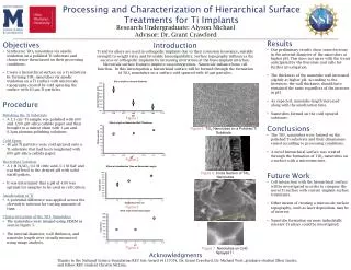
SURFACE PROCESSING OF AN IRIDIUM ALLOY FOR CONTROL OF EMISSIVITY. E.K. Ohriner, W. Zhang, G.B. Ulrich, and R. G. Miller Materials Science and Technology Division Oak Ridge National Laboratory TMS Annual Meeting Refractory Metals 2011 San Diego, CA February 28, 2011. Outline.

E N D
SURFACE PROCESSING OF AN IRIDIUM ALLOY FOR CONTROL OF EMISSIVITY E.K. Ohriner, W. Zhang, G.B. Ulrich, and R. G. Miller Materials Science and Technology Division Oak Ridge National Laboratory TMS Annual Meeting Refractory Metals 2011 San Diego, CA February 28, 2011
Outline • Surface geometry effects on emissivity of iridium • Grit Blasting • process parameters • effects on surface geometry • Modeling of grit blast • surface geometry • plastic strain • Effect of grit blasting on grain growth during subsequent heating • Conclusions
Elevated Temperature Total Hemispherical Emissivity of Iridium Clean iridium Oxidized in air 1 hr at 1363°C 4 hrs at 882°C 8 hrs at 882°C 34 hrs at 882°C From Report GESP-7071 (June 1971)
Effect of Surface Preparation on Emissivity of Iridium Test temperature 423 K From Wladimir Sabuga and Reinhard Todtenhaupt, High Temperatures-High Pressures, Vol. 33, (2001) p. 265
Emissivity of Pure Iridium Depends on Surface Slope Not Roughness Test temperature 423 K From W. Sabuga et al.
Effect of Grit Blasting on Emissivity of Iridium DOP-26 Alloy (Ir-0.3%W-0.006% Th-0.005% Al)
Grit Blast of Iridium Alloy Stand Off Distance Grit Blast Cabinet
Grit Blast of Iridium Alloy • Recrystallized at 1650 K • Grit blast with WC media • Mesh size 100 to 200 µm • 50 ± 5 psig air pressure • 425 grams average sprayed in 25 s • Spray area about 15 cm2 • 8-mm (5/16”) diameter nozzle • Nominal 10 cm (4”) standoff distance WC grit
Effect of Air Pressure and Standoff Distance on Particle Velocity Minimum Measured Particle Velocity Maximum Measured Particle Velocity
Simplified Finite Element Modeling of Grit Blasting of an Iridium Alloy • A single tungsten carbide (WC) particle impact on an iridium disc is simulated. • The WC particle is assumed to be rigid. • Impact velocities are 20, 30, 40 and 60 m/s. • The WC particle is approximated using three different geometries but with the same mass: • A sphere with a radius of 79.5 µm • A cone with a tip angle of 60 degree • A cone with a tip angle of 100 degree
Axisymmetric Model And Mesh Spherical WC particle Iridium material
Distribution Of Plastic Strain After A Single Impact on With Spherical Particle * Red color represents plastic strain more than 2.5% 50 µm 50 µm Impact velocity = 30 m/s Impact velocity = 20 m/s Impact velocity = 40 m/s Impact velocity = 60 m/s
Distribution Of Plastic Strain After A Single Impact With Conical Particle Having 100° Tip Angle * Red color represents plastic strain more than 2.5% 50 µm 50 µm Impact velocity = 20 m/s Impact velocity = 30 m/s Impact velocity = 40 m/s Impact velocity = 60 m/s
Distribution Of Plastic Strain After A Single Impact With Conical Particle Having 60° Tip Angle * Red color represents plastic strain more than 2.5% 50 µm 50 µm Impact velocity = 20 m/s Impact velocity = 30 m/s Impact velocity = 40 m/s Impact velocity = 60 m/s
Model Results Show Increased Depth of Penetration with Angularity
Model of Surface Using Square Array of Adjacent Impacts • Calculation of surface roughness arithmetic average (AA) and root mean square (RMS) slope or angle • Solid geometry formulas A Cross section – spherical indenter A A top view Cross section – conical indenter A
Surface Slope Depends on Grit Shape and Not Surface Roughness
Comparison of Model and Experimental Results for Grit Blasting • Average roughness of grit blast surface is somewhat lower than model prediction • attributed to absence of overlapping impacts in the model • At equivalent particle velocity the measured average surface slope is midway between that predicted for spherical particle and oblique faceted particle (100° cone) • qualitatively consistent with the range of grit shapes, including large faceted particles, multiple small facets, and spherical • At equivalent surface roughness the measured average surface slope is midway between that predicted for spherical particle and oblique faceted particle (100° cone)
Grit Blast Produces Region of Subsurface Plastic Strain • Observed by metallography to extend to about 20 µm • Can produce local recrystallization (1523 K/ 1hour)
Subsurface Grain Growth With Limited Bulk Grain Growth at Higher Temperatures 1648 K for 1 hour 1773 K for 1 hour
Effect of Grit Blasting on Grain Size in Subsurface Region Following 1 Hour Recrystallization
No Abnormal Grain Growth in Region of Grit Blasted Surface for Exposure At Very High Temperature 2173 K for 1 minute 2173 K for 2 hours
Conditions For Abnormal Grain Growth Not Produced By Grit Blasting • Large local strains at surface • Prior plastic strain in critical range 2% to 10% does not exist over large area as is the case for bending • Free surface limits grain enlargement 5% prior bend strain no prior strain 1550 K / 1 hr + 1225 K /1 month +1600 K / 3months + 1850 K /3 min (From McKamey et al. 2002)
Conclusions • Simplified model results correlate with measured surface slope and roughness • Emissivity determined primarily by average slope of surface rather than average roughness • Surface roughness increases nearly linearly with grit velocity • Average surface slope varies little with grit velocity • Average surface slope is controlled primarily by particle shape • Strains from grit blasting can lead to localized recrystallization but do not cause abnormal grain growth
Acknowledgments • Support of Office of Space and Defense Power Systems, U. S. Department of Energy, under Contract DE-AC05-00OR22725 with UT-Battelle, LLC. • Larry Walker, Hu Longmire, Brian Walls of ORNL for microscopy and surface measurement. • Bill Barker of Progressive Technologies for particle velocity measurements