Download
1 / 17
170 likes | 503 Views
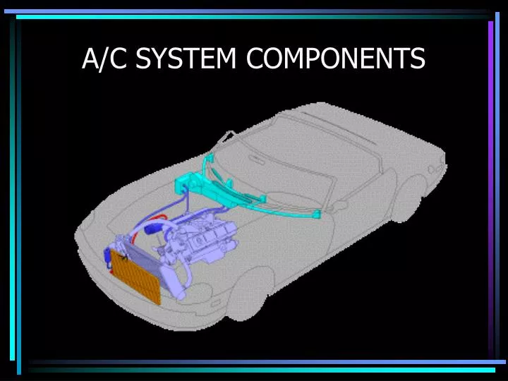
A/C SYSTEM COMPONENTS. The Refrigeration Cycle. Refrigeration – To remove heat by mechanical means Refrigerant – Chemical compound used in a refrigeration system to carry heat Refrigeration Cycle – Repeatedly changing refrigerant from a liquid to a vapor & vapor to liquid to remove heat.

E N D
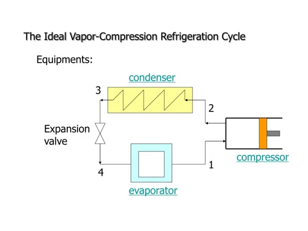
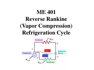
The Refrigeration Cycle • Refrigeration – To remove heat by mechanical means • Refrigerant – Chemical compound used in a refrigeration system to carry heat • Refrigeration Cycle – Repeatedly changing refrigerant from a liquid to a vapor & vapor to liquid to remove heat
Compressor • Refrigerant pump • Increases Pressure & Temperature • Separates High & Low sides of system • Oil stored in Crankcase (sump)
Compressor Malfunctions • Malfunctions evident in following ways: • Noise • Seizure • Leaks • High inlet & low discharge pressures
Discharge Hose • CONTAINS HIGH PRESSURE. • SYNTHETIC RUBBER WITH NYLON BARRIER LINING. • 13/32 ID. • PREFORMED METAL ENDS WITH FITTINGS.
Condenser • Heat exchanger. • Liquefies heat laden vapor • Hot vapor enters at top of condenser • Hot liquid leaves at bottom
Conventional Tube and Fin • Parallel Two Path. • Mechanically expanded tube to fin joints. • Circular Tubes.
Serpentine Tube and Center Condenser • Brazed tube to fin joints. • Flat Tubes. • Parallel two path flow.
Multi-Louver Fin Design • Manifolded Multi-path refrigerant flow.
Evaporator • Dehumidifies the airstream. • Under ideal conditions, refrigerant boils to complete saturation 3/4 of the way through Evaporator. • Flooded evaporator means is full of liquid refrigerant with no room for expansion. • Starved evaporator means all refrigerant is boiled in the first quarter of the evaporator.
Receiver -Drier • Stores reserve liquid refrigerant • Ensures vapor-free liquid to the thermostatic expansion valve (TXV). • Located on the high side of the system. • Contains a desiccant that absorbs moisture.
Thermostatic Expansion Valve • Located on inlet side of evaporator. • Used to control evaporator temp. • Variable orifice can vary on pressure, temperature or both. • Can malfunction in open or closed position.
Orifice Tube • Calibrated Restrictor • Different color = different Orifice size. • Mesh Filter Screen. • Meters refrigerant into evaporator as low pressure liquid.
Accumulator • Located between evaporator and compressor (low side) • Primary function is to separate the vapor from the liquid and oil. • Location for desiccant.