Download
1 / 39
390 likes | 499 Views
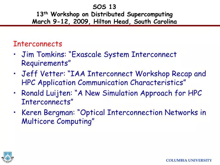
SOS 13 13 th Workshop on Distributed Supercomputing March 9-12, 2009, Hilton Head, South Carolina. Interconnects Jim Tomkins: “Exascale System Interconnect Requirements” Jeff Vetter: “IAA Interconnect Workshop Recap and HPC Application Communication Characteristics”

E N D
SOS 1313th Workshop on Distributed SupercomputingMarch 9-12, 2009, Hilton Head, South Carolina Interconnects • Jim Tomkins: “Exascale System Interconnect Requirements” • Jeff Vetter: “IAA Interconnect Workshop Recap and HPC Application Communication Characteristics” • Ronald Luijten: “A New Simulation Approach for HPC Interconnects” • Keren Bergman: “Optical Interconnection Networks in Multicore Computing”
Optical Interconnection Networks in Multicore Computing Keren BergmanColumbia University SOS 13 13th Workshop on Distributed Supercomputing March 9-12, 2009, Hilton Head, South Carolina
CMPs: motivation for photonic interconnect Growing multi-core architectures straining on-chip and chip-to-chip electronic interconnects CELL BE 9 cores IBM 2005 Montecito 2 cores Intel 2004 Niagara 8 cores Sun 2004 Terascale 80 cores Intel Polaris 2007 Barcelona 4 cores AMD 2007 Tile64 64 cores Tilera 2007 Photonics provide solution to bandwidth demand for on- and off-chip communication Silicon on insulator platform for photonic interconnection networks features high index contrast and compatibility with CMOS fabrication
Global On-Chip Communications • Growing number of cores Networks-on-Chip (NoC) • Shared, packet-switched, optimized for communications • Resource efficiency • Design simplicity • IP reusability • High performance • But no true relief in power dissipation • IBM Cell ~30-50% of chip power budgetallocated to global interconnect
Off-Chip Communications • Higher on-chip bandwidths more off-chip communication • Off-chip bandwidth scales through pin count & signaling rate • Pin counts limited by packaging constraints, chip size, and crosstalk • Power scales badly with signaling rates Memory InterfaceController 25.6 GB/s @ 3.2GHz I/O Controller 25 GB/s @ 3.2GHz(inbound) [Kistler et al., IEEE Micro26 (3) 10–23 (2006)] 5
Off-Chip Communications Element Interconnect Bus(on-chip communications) delivers nearly an order of magnitude more bandwidth: 205 GB/s @ 3.2 GHz Memory InterfaceController 25.6 GB/s @ 3.2GHz I/O Controller 25 GB/s @ 3.2GHz(inbound) [Kistler et al., IEEE Micro26 (3) 10–23 (2006)] 6
Why Photonics? Photonics changes the rules for Bandwidth-per-Watt. ELECTRONICS: • Buffer, receive and re-transmit at every router. • Each bus lane routed independently. (P NLANES) • Off-chip BW requires much more power than on-chip BW. Photonics: • Modulate/receive ultra-high bandwidth data stream once per communication event. • Broadband switch routes entire multi-wavelength stream. • Off-chip BW = on-chip BW for nearly same power. RX RX RX RX RX TX RX TX TX TX TX TX 7
Silicon Photonic Integration MIT, 2008 Cornell, 2005 IBM, 2007 Luxtera, 2005 UCSB, 2006 8
Vision of Photonic NoC Integration photonic NoC 3D memory layers multi-core processor layer 9
Nanophotonic Interconnected Compute/DRAM Node DRAM DRAM DRAM DRAM DRAM DRAM DRAM DRAM
P P P G G G P P P G G G P P P G G G Hybrid NoC Approach • Electronics • Integration density abundant buffering and processing • Power dissipation grows with data rate and distance • Photonics • Low loss/power, high bandwidth,bit-rate transparent • Limited processing, no buffers • Our solution: a hybrid approach • Data transmissionin a photonic network • Control in an electronic network • Circuit switched paths reservedbefore transmission(no optical buffering required)
P P P P P P P P P G G G G G G G G G Thin Electrical Control Network (~1% BW, small messages) Photonic NoC Deflection Switch Hybrid NoC Demo Processing Core (on processor plane) Gateway to Photonic NoC (between processor & photonic planes) DARPA phase I ICON project
Cornell HIGH-SPEED MODULATOR Key Building Blocks HIGH-SPEED RECEIVER LOW LOSS BROADBAND NANO-WIRES 5cm SOI nanowire 1.28Tb/s (32 l x 40Gb/s) IBM IBM/Columbia BROADBAND MULTI-l ROUTER SWITCH IBM Cornell/ Columbia
Microring Resonators Valuable building blocks for SOI-based systems Passive operations Filtering and multiplexing Active functions Electro-optic, thermo-optic, all-optical switching/modulation B. E. Little et al., PTL, Apr 1998 Q. Xu et al., Opt. Express, Jan 2007 P. Dong et al., CLEO, May 2007
Basic Switching Building Blocks Broadband 1×2 Switch Through State Drop State A. Biberman, OFC 2008 Broadband 2×2 Switch Cross State Bar State B. G. Lee, ECOC 2008
Transmission Switch Operation bar in0 out0 cross PUMPING in1 out1 16
Multi-wavelength Switch Block Truly broadband switching of multi-wavelength packets using a single switch Single Wavelength Switch P dissipated,single wavelength = P dissipated,multi-wavelength Multi-Wavelength Switch
Broadband Switching A. Biberman, LEOS 2007 ••• ••• ••• Wavelength ••• ••• Ring FSR ••• ••• A. Biberman, ECOC 2008 ••• ••• Time A. Biberman, OFC 2008 Broadband data signal
Non-Blocking 4×4 Switch Design N • Original switch:internally blocking • New design: • Strictly non-blocking* • Same number of rings • Negligible additional loss • Larger area • * U-turns not allowed N W E W E S S 19
Simulation Environment Simulation Planes • Highest level of simulation – enables system-level analysis • Composed of functional components and building blocks • Source plane – Traffic generator for application specific studies • Enables system performance analysis based on physical layer attributes • Plug-ins for simulator • ORION – Electronic Energy Model • DRAMSim – Memory Simulator • SESC – Architecture Photonic Plane Control Plane Source Plane 21
Photonic Elemental Building Blocks • Foundation of Simulation Structure • Accurate physical layer model • Parameterized – current and projected performance 1×2 Switch Crossing 2×2 Switch • Parameter Space • Latency • Insertion loss • Crosstalk • Resonance profile • Thermal dependence Modulator 22
1x2 Photonic Switching Element Through Port Insertion Loss:* 0.063 dB Extinction Ratio: 25 dB Propagation Latency: 1 ps 75 μm 50 μm Insertion Loss and Crosstalk Measurements Drop Port 75 μm Insertion Loss*: 0.513 dB Extinction Ratio: 20 dB Propagation Latency: 4.1 ps [P. Dong, Opt. Exp., July 2007] * includes crossing and propagation loss
Waveguide Crossing 50 μm 50 μm Insertion Loss Measurements * includes crossing and propagation loss Insertion Loss*: 0.058 dB Propagation Latency: 0.6 ps [W. Bogaerts, Opt. Let., Oct. 2007] Reflection Loss: -22.5 dB Reflection Latency (from Original Signal Injection): 0.6 ps
Modulator Cascaded Wavelength-Parallel Micro-Ring Modulators 3 μm 11 μm 4- × 4-Gb/s Eye Diagrams 13 μm Peak Power Insertion Loss*: 0.002 dB Average Power Insertion Loss*: 3.002 dB Extinction Ratio: 20 dB Propagation Latency: 100 fs Ideal energy dissipation: 25 fJ/bit [Q. Xu et al., Opt. Exp., Oct. 2006]
Detector/Receiver Detector Sensitivity: -20 dBm Energy dissipation: 50 fJ/bit [Koester et al., JLT, Jan. 2007]
Modeling Functional Components • Higher order structures made from building blocks • Underlying logic for switching functionality • Size and position of blocks specified at this level • Physical layer captured by aggregate performance of blocks [M. Lipson et al., Cornell University] 28
Optical Interconnection Network Simulator Photonic Plane Processing Element Plane Electronic Plane
Photonic Plane • Detailed layouts of WG’s, crossings, ring resonators, modulators and detectors • Characterization of devices by measurement in lab, including insertion loss, extinction ratio, and power dissipation • Automated insertion loss analysis, and power consumption tabulating
Electronic Plane • Router functions in cycle-accurate OMNeT++ • Router power and area calculated with ORION power model • Approximate layout based on die size and router area yielding lengths of wires, affecting power dissipation
Optical I/O • Gateway modified at the periphery to allow switching off chip from either the local access node or the external network
Optical DRAM Access • DRAM interface – a detector bank controls a multi-wavelength switch for writing using striped wavelengths across multiple DRAM chips. Reading is similar. • Functional and power modeling of DRAM accomplished by integrating DRAMsim (UMD)
Network Performance: Random traffic 8x8 network with random traffic (poisson arrival, uniform src-dest) Photonic network = blocking torus with 20 wavelengths • Conclusions: • A blocking torus out-performs an electronic network around ~250B messages • A size filter is useful for utilizing the electronic network for small messages
Network Performance Results • Optical loss budget, dependent on device limitations: • Injected optical power (device nonlinear threshold) • Network insertion loss • Receiver sensitivity • Physical performance drives system performance: • Bandwidth (related through the number of allowed wavelengths and injection power) • Network scaling (due to limitations on insertion loss) • Network size/performance scales with technology improvements Blocking Torus Network Scaling with 65% Improvement in Crossing Loss Blocking Torus Network Scaling with Current Parameters Number of Wavelengths Number of Network Nodes 38
Summary and Next Steps • Nanoscale silicon photonics opportunity • System wide uniform bw • Energy efficiency • Vast design space across: • Photonic and electronic phy layer • Network architecture • System performance • Building library of components with accurate capture of physical layer in integrated simulation platform • Simulator environment for interconnection network which is critical middle layer: • Design exploration of networking architectures with functional building blocks – CAD-like environment • Direct interface to system/application performance evaluation • Integrated system-network-device design exploration tool set