Download
1 / 44
510 likes | 871 Views
Diffraction Basics. The qualitative basics:. Coherent scattering around atomic scattering centers occurs when x-rays interact with material In materials with a crystalline structure, x-rays scattered in certain directions will be “in-phase” or amplified

E N D
Diffraction Basics The qualitative basics: • Coherent scattering around atomic scattering centers occurs when x-rays interact with material • In materials with a crystalline structure, x-rays scattered in certain directions will be “in-phase” or amplified • Measurement of the geometry of diffracted x-rays can be used to discern the crystal structure and unit cell dimensions of the target material • The intensities of the amplified x-rays can be used to work out the arrangement of atoms in the unit cell
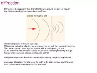
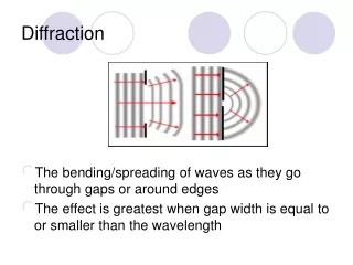
The chief result of the interaction of X-rays with atomsin the specimen isscattering Scattering is the emission of X-rays of the same frequency (energy) as the incident X-rays in alldirections (but with much lower intensity)
The Generalized 2D Laue Equation: (h is the order of the diffraction, here 0 or 1)
In the specialized case where the angle of incidence is 90° the equation becomes:
For a two-dimensional lattice array of atoms, the Laue equations are:
The Laue diffraction cones for the A and B directions are shown below:
Diffraction will only occur when the diffraction angles define the same direction. In the case below this is when the cones intersect to form the lines OX and OY
In a three-dimensional lattice array, there will be multiple Laue diffraction cones. Below a simple diagram shows three first order cones in ABC space
There are now three Laue equations requiring a simultaneous solution (i.e., there must be a diffraction direction common to all three cones): • A unique solution is difficult to obtain • In Laue diffraction, the crystal is fixed and oriented with a lattice axis parallel to the beam • is varied by using “white” radiation • With monochromatic radiation, movement of the crystal is required for diffraction to occur
The Bragg Law X-ray beam encounters a 3-d lattice array at left. Assume the following: • A third-order cone about OA • A second-order cone about OB • A first-order cone about OC We assume these cones intersect at a common line satisfying the diffraction condition.
The rays scattered by adjacent atoms on OA atoms have a path difference of three wavelengths • Those about OB have a path difference of two wavelengths • About OC, one wavelength difference • These points of coherent scatter define a plane with intercepts 2a, 3b, 6c (A’’, B’’, C’’) and a Miller index of (321)
The Bragg Law “bottom line”: A diffraction direction defined by the intersection of the hth order cone about the a axis, the kth order cone about the b axis and the lth order cone about the c axis is geometrically equivalent to a reflection of the incident beam from the (hkl) plane referred to these axes. in other words: Diffraction from a lattice array of points may be functionally treated as reflection from a stack of planes defined by those lattice points
On the previous diagram, the “reflected” rays combine to form a diffracted beam if they differ in phase by a whole number of wavelengths, that is, if the path difference AB-AD = n where n is an integer. Therefore and
, n is the order of diffraction In the Bragg Law, Above are 1st, 2nd, 3rd and 4th order “reflections” from the (111) face of NaCl. By convention, orders of reflections are given as 111, 222, 333, 444, etc. (without the parentheses)
The Reciprocal Lattice Problems addressed by this unusual mental exercise: • How do we predict when diffraction will occur in a given crystalline material? • How do we orient the X-ray source and detector? • How do we orient the crystal to produce diffraction? • How do we represent diffraction geometrically in a way that is simple and understandable?
The first part of the problem • Consider the diffraction from the (200) planes of a (cubic) LiF crystal that has an identifiable (100) cleavage face. • To use the Bragg equation to determine the orientation required for diffraction, one must determine the value of d200. • Using a reference source (like the ICDD database or other tables of x-ray data) for LiF, a = 4.0270 Å, thus d200 will be ½ of a or 2.0135 Å. • From Bragg’s law, the diffraction angle for Cu K1 ( = 1.54060) will be 44.986 2. Thus the (100) face should be placed to make an angle of 11.03 with the incident x-ray beam and detector. • If we had no more complicated orientation problems, then we would have no need for the reciprocal space concept. • Try doing this for the (246) planes and the complications become immediately evident.
The second part of the problem Part of the problem is the three dimensional nature of the diffracting planes. They may be represented as vectors where dhkl is the perpendicular from the origin to the first hkl plane: While this is an improvement, the graphical representation is still a mess – a bunch of vectors emanating from a single point radiating into space as shown on the next slide ----
Ewald proposed that instead of plotting the dhkl vectors, that the reciprocal vector be plotted, defined as: • The units are in reciprocal angstroms and defines a reciprocal space. • The points in the space repeat at perfectly periodic intervals, defining a space lattice called a reciprocal lattice • Figure 3.3 can now be reconstructed plotting the reciprocal vectors instead of the dhkl vectors • The comparison is shown in the following slides
Any lattice vector in the reciprocal lattice represents a set of Bragg plans and can be resolved into its components: In orthogonal crystal systems, the d and d* are simple reciprocals. In non-orthogonal systems, the reciprocals (since they are vectors) are complicated by angular calculations Because the angle is not 90, the calculation of d* and a* involve the sin of the interaxial angle.
The table below shows the relationships between axes in direct and reciprocal space. At the bottom is a very complex trigonometric function that defines the parameter V used in the triclinic system.
Figure 3.7 shows the arrangement where the (230) point is brought into contact with the Ewald sphere. By definition and hence from the definition of the reciprocal vector The BraggRelationship! substitution yields:
The Powder Diffraction Pattern • Powders (a.k.a. polycrystalline aggregates) are billions of tiny crystallites in all possible orientations • When placed in an x-ray beam, all possible interatomic planes will be seen • By systematically changing the experimental angle, we will produce all possible diffraction peaks from the powder
There is a d*hkl vector associated with each point in the reciprocal lattice with its origin on the Ewald sphere at the point where the direct X-ray beam exists. • Each crystallite located in the center of the Ewald sphere has its own reciprocal lattice with its orientation determined by the orientation of the crystallite with respect to the X-ray beam
The Powder Camera The Debye-Scherrer powder camera
Debye diffraction rings from the d*100 reflection. Note the 1st and 2nd order cones, and “back” reflections
The Powder Diffractometer • Think of the diffractometer as a device for measuring diffractions occurring along the Ewald sphere – it’s function is to move all of the crystallites in the powder and their associated reciprocal lattices, measuring diffractions as they intersect the sphere • Because of the operational geometry of diffractometers, there must be a very large number of small crystallites (a.k.a., “statistically infinite amount of randomly oriented crystallites”) for the diffractometer to “see” all of the possible diffractions • By convention (but not by accident – note Fig 3.7) diffraction angles are recorded as 2. Data are commonly recorded as 2 and intensity
Conclusions The geometry of powder diffraction is best understood through the use of the reciprocal lattice and the Ewald sphere The powder diffractometer is a device for directly applying these “constructions” to measure d-spacings in crystalline materials X-ray diffraction allows direct measurement of the lattice Much information about the crystal structure can be obtained from variations in intensity (and the complete some “reflections” in the pattern)
Next week: Diffraction Intensity: The rest of the fingerprintOrigin, Variations, Extinctions and Error Sources in diffraction experiments