Download
1 / 11
160 likes | 969 Views
AT&T Voice Over Managed Services Service Line: MISBIB BIB / BVoIP IP Flex Reach IP-PBX ANALOG VoMIS IP Local Site Documentation Package. Case#: SDD:. Technical Contact Name: Site Address: Site Suite & Building: Site City & State: Contact Phone:. CPE Ship To Location & Contact:.

E N D
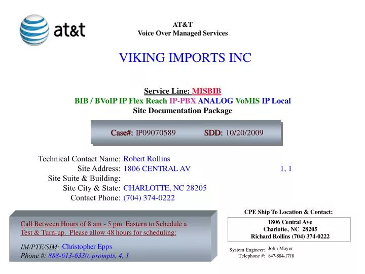
AT&T Voice Over Managed Services Service Line: MISBIB BIB / BVoIP IP Flex Reach IP-PBXANALOG VoMIS IP Local Site Documentation Package Case#: SDD: Technical Contact Name: Site Address: Site Suite & Building: Site City & State: Contact Phone: CPE Ship To Location & Contact: Call Between Hours of 8 am - 5 pm Eastern to Schedule a Test & Turn-up. Please allow 48 hours for scheduling: IM/PTE/SIM: Phone #: 888-613-6330, prompts, 4, 1 System Engineer: Telephone #:
SHEET NO. 2 3 4 5 6 7 & 8 9 10 11 DESCRIPTION TABLE OF CONTENTS EQUIPMENT ORDER LIST (EOL) AT&T / Edgemarc Hardware & Cable Detail ROUTER CABLING AND ADDRESSING DIAGRAM IP Flex Reach Analog FXS Ports BIB Base Unit to Add-On Device Connectivity Chart. 12-Port PoE (Base Unit Router) Back Panel. 12-Port PoE (Base Unit Router) Front Panel. 8-Port ATA (4508E) Analog Expansion Module. REVISION 1.0 1.0 1.0 1.0 1.0 1.0 1.0 1.0 1.0 TABLE OF CONTENTS Attention Customer: The equipment you received has already been configured. Please do not attempt to re-configure this Equipment.
AT&T / Edgemarc Hardware & Cable Detail 4508E (8 Port ATA) Analog Expansion Module Hardware & Cables included with each device. 4508T4WPoE 12 or 24 Port Base Router Hardware & Cables included with each device • - Power Pack 3.75 Amps. • A/C Power cord ( 6 ft.). • Wireless Antenna. • 2 “L” shaped mounting brackets & 8 small philips mounting screws. • 4 holes for Mounting to unit, 2 Elongated holes for rack mounting. • Brackets may be pre-installed. • One T1 cable. Grey in color. 14 feet in length, • (RJ45 male - RJ45 male) with a tape labeled T1 at each end . • - One V.90 Cable. • Brown in color. 14 feet in length, (RJ11 male - RJ11 male) with • a tape labeled V.90 at each end. • Power Pack 1.0 Amps. • - A/C Power cord ( 6ft. ). • 2 long “L” shaped mounting brackets & 6 small philips mounting screws. • 3 Mounting holes to unit, 2 Elongated holes for rack mounting. • Brackets may be pre-installed. • - One V.90 Cable. Brown in color. • 14 feet in length, (RJ11 male- RJ11 male) with a tape labeled V.90 • at each end. • - One Ethernet Cable. Burnt Orange in color. • 14 feet in length, (RJ45 male- RJ45 male) with a tape labeled Ethernet at • each end. • - 1 plastic bag containing one black 4” pull tie and six 5/8” philips screws. • 1 plastic bag containing one 1” square piece of foam tape, and plastic • cable holder for pull tie. • -1 faceplate template for wall mounting.
ROUTER CABLING DIAGRAM 4 2 3 1 Host Names 4508E (ATA) ATA #1 - USVIKICLTNC07S IP ADDRESS CONFIGURATION INFORMATION: WAN IPAddress: ________ /30 Voice VLAN 100: 1.1.2.1 /24 Data VLAN 200: 192.168.4.1 /22 AT&T Public Signaling IP Address: Public Network Customer VLAN 300: Lan IP: Subnet: Management VLAN 500 /28 Internal IP Address: 172.16.10.10 Antenna Range 300 Feet Base Router Host Name 4508T4WPoE12 AT&T T1.5 CKT ID(s): - Port 1 T1 NETWORK FACILITY Ethernet WAN port not used 56941-025-262 (ISE642-025) USB Ports Not Used V.90 TO 2-WIRE DIAL-UP LINE To Be Provided GCBSR2-J11J11-22mo4 Maintenance Option: M4 M4 (7X24, Four Hour Response)
12-Port PoE Base Unit Router Front Panel 6 4 2 3 5 1 FXS ports Circled. 6 Ports used for connecting to voice devices. Analog Phones and Equipment Ports 1-6 (Circled) outlined in green)) are to be connected to phones, analog PBX/key systems and fax machines for the VoIP service provide by Office in a Box. During the telephone install process you will be directed to connect to your phones and/or fax machines. IP Flex Reach Analog FXS Ports Attention Customer: The equipment you received has already been configured. Please do not attempt to re-configure this Equipment.
BIB Base Unit to Add-On Device Connectivity Chart Attention Customer: The equipment you received has already been configured. Please do not attempt to re-configure this Equipment.
BIB Base Unit to Add-On Device Connectivity Cont… Attention Customer: The equipment you received has already been configured. Please do not attempt to re-configure this Equipment.
12-Port PoE (Base Unit Router) Back Panel 1). Connect a gray RJ-45 14' T1 straight-through cable to the region denoted as “F” of the 24-Port PoE Base Unit Router Back Panel. 2). Connect the other end to a T1 demarcation point.
12-Port PoE (Base Unit Router) Front Panel 3). If you will be using the wireless LAN, connect the wireless antenna to the front of the Base Unit Router as shown in region “A” of the 12-Port PoE Base Unit Router Front Panel. 4). Connect the appliance from region B, 12-Port PoE Base Unit Router Front Panel to an AC outlet.
8-Port ATA (4508E) Analog Expansion Module WAN Port (PVID 100) LAN Port 3 (PVID 500) 1). Connect one end of the orange RJ-45 cable provided with the analog expansion module to the highest numbered port (located in region “B” of the 24-Port PoE Base Unit Router Back Panel of the switch. Connect the other end to the Ethernet port (labeled as “A” in Figure 9. 8-port analog expansion module) on the analog expansion module. 2). If more than one analog expansion module will be used, connect another RJ-45 cable to the highest numbered port (located in region “B” of the 24-Port PoE Base Unit Router Back Panel of the switch. Connect the other end to the Ethernet port (labeled as “A” of the 8-port analog expansion module) on the analog expansion module. Connect up to three 8-port analog expansion modules, repeating steps 1 and 2 accordingly. Following the guidelines at the beginning of this section, connect each appliance from region B of the. 8-port analog expansion module to an AC outlet