Download
1 / 19
190 likes | 300 Views
ASIRAS Pre Report. Part 1: ASIRAS campaigns 2004 System characteristics Data acquisition Part2: preliminary data processing report GPS processing 1st results of the comparison of Laser and Radar INS correction Summary and Questions Future prospects.

E N D
ASIRAS Pre Report • Part 1: ASIRAS campaigns 2004 • System characteristics • Data acquisition • Part2: preliminary data processing report • GPS processing • 1st results of the comparison of Laser and Radar • INS correction • Summary and Questions • Future prospects
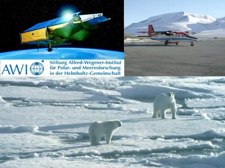
Cal/Val – ASIRAS and Laser Scanner as main tools ASIRAS: Airborne synthetic interferometric radar altimeter system
Summary description of system 1 + 2 GPS Antennen für Trimble 7 Radar Altimeter 8 INS 9 GNS-X 10 Power Distribution Module 11 Data Distribution Module 12 Rack I 13 Rack II 15 Basis Meteorology Sensors 16 BMET I/O Module 17 Fiber Optic 18 Riegl Laser Scanner LMSQ280 19 Riegl LD90 Laser Altimeter 20 Sony Video Camera 21 RST - ASIRAS Antenna 22 Antenna Cable Slot
System characteristics ASIRAS: altitude: Minimum altitude: 1090m, angle of beam: - along track: 10° - across track: 2.5° footprint: 38 meter (1150 meter flight altitude) Laser scanner: altitude: Maximum altitude: 1200m, scanning range: +/- 22.5 ° = 45 ° total footprint: 880 meter (1150 meter flight altitude) 270 meter (350 meter flight altitude) Consequence: fly each track twice in low (laser scanner, 350 m) and high altitude (ASIRAS + laser scanner, 1150 m)
GPS Processing Difference of pre and final processed GPS data Profile A040420_04 (Austfonna) Height Longitude Latitude
Surface elevation of Laser and Radar Runway: Part of Profile A040420_00 ca. 2400 m Difference Laser - Radar Roll and Pitch
Surface elevation of Laser and Radar Part of Profile A040420_04 W E ca. 600 m Difference Laser - Radar Roll and Pitch
1st results of the comparison between Laser and Radar • Profile N-S: A040420_01 • Profile W-E: A040420_04 A040420_04 A040420_01 Pic. from Norwegian ground operating team
Surface elevation of Laser and Radar Profile A040420_04 W E ca. 85 km Difference Laser - Radar Roll and Pitch
1st results of the comparison between Laser and Radar Difference between INS corrected Laser and INS corrected Radar Surface elevations Difference between INS corrected Laser and INS corrected Radar Surface elevations as a function of Pitch
1st results of the comparison between Laser and Radar Surface elevation - Profil A040420_04 Difference between INS corrected Laser and INS corrected Radar Surface elevations Difference between INS corrected Laser and INS (without Pitch correction) corrected Radar Surface elevations Pitch
Summary and Questions • Difference between Laser and Radar over a runway is ca. 27 cm: • Q: Is this created by a static shift (eg. Cable length are different) or is the Radar squinting? (27 cm ---> squint angle: 1.24 degree (1150 m flight altitude over ground) • Q: If the radar is squinted along track, how is this effecting the Laser-Radar difference and how can this be corrected? • Difference between Laser and Radar over flat snow surface is ca. 45cm • Q: Does this imply a penetration of radar waves into the snow pack of ca. 20 cm? • Sensitivity of Laser and Radar to the pitch is different. • Best results for profile A040420_04 when: • Laser is corrected for roll, yaw and pitch. • Radar is corrected for roll and yaw without pitch • Q: Where is the high variability (about 1-2 m) of the difference between laser-radar surface elevation coming from? • Q: Why do we see penetration of laser instead of radar in some parts of the profile?
Future prospects • Evaluate the Laser scan data – DEM. • Include the comparison between radar and laser-scan data. • Check the INS correction with the laser scanner. • Find an explanation for the elevation difference of radar and laser (27 cm). • Investigate the form of the radar echo - can we distinguish between accumulation, percolation and ablation zone? • Corner reflector - How deep is the radar penetrating the snow pack? • Include ground measurements to validate the airborne data.