Download
1 / 42
420 likes | 514 Views
INC 112 Basic Circuit Analysis. Lecturer Assistant Prof. Dr. Poj Tangamchit. About the Instructor. Office: CB40603 (CB4 6 th floor) Control System and Instrumentation Eng. (INC) Tel: x-9094 E-mail: poj.tan@kmutt.ac.th Research Interest: Robotics, Artificial Intelligence (AI)

E N D
INC 112 Basic Circuit Analysis Lecturer Assistant Prof. Dr. Poj Tangamchit
About the Instructor Office: CB40603 (CB4 6th floor) Control System and Instrumentation Eng. (INC) Tel: x-9094 E-mail: poj.tan@kmutt.ac.th Research Interest: Robotics, Artificial Intelligence (AI) Lecture: Self-lecture. Reading material before coming to class is encouraged.
Freshmen’s Requirements • Computer INC160 • Software INC151 • Circuit INC112
Course Details • 3 Credits • Class time 3 hours / week • Review + Homework 6 hours/week • E-learning material (DVD) is provided
Scoring & Grading Midterm Exam 35% Final Exam 35% Homework, assignment 20% Quiz (Pop quiz) 10% Grading follows the faculty of Engineering’s standard procedure.
Homework & Quiz Homework takes time. Allocate 6-12 hours each week for it. Students need self-study outside class time.
Course Webpage http://www.inc.eng.kmutt.ac.th/inc112 • Lecture Slides • Homework • Homework/ Quiz Solutions • Announcements
Textbook Engineering Circuit Analysis, 7th edition McGrawHill William H. Hayt Jr.,Jack E. Kemmerly,Steven M. Durbin
How to read a Textbook • Book Overview • Read Index • Think about what should be in each chapter • Think about what each chapter relate to each other • Chapter Focus • Read the title of each section, Guess what it will say • Look at pictures and description • Read equations and Math parts • Reread the section that you want to know more
Electricity Electricity is a result from the flow of electrons. electricity Note: Electricity flows in the opposite direction of electron flow. = electron
Electric Current vs. Electron Current - + + - = Atom Structure - + + - - + + - - + + + + - - - + + electricity
Metaphor Electricity is similar to water flow. Water flows from high level to low level. Electricity flows from high voltage to low voltage. High Voltage Low Voltage
strong(fast, high kinetic energy) • amount of water • Voltage • Current Measurement of Electricity Since we use electricity to do work for us, how Can we measure its energy? How can we measure the water power? Think about a water gun. High Voltage Low Voltage
Electric Potential (ศักย์ไฟฟ้า) Which water drop has more impact force at the ground? Potential Energy(Height) transform Kinetic Energy (Velocity) Electric potential can be compared with the height of the water drop from the reference ground
Ground: Reference Point Normally, we measure height compared to the sea level. Also, electric potential at a point can be measured compared to the electric potential at the ground. Unit: Volt (V) Electric potential, or voltage has a unit “volt”. Ground always has 0 volts.
Voltage (ความต่างศักย์) Voltage is a difference of electric potential between 2 points Unit: Volt Compare to the height of 2 water drops
Electric Current (กระแส) Low current High current
Electric Current Unit Unit: Ampere, Amp (A) Note: Both current and voltage have directions
What is Circuit Analysis about? To calculate voltage or current at some points and some time in electric circuits
Course Overview DC (Direct current) AC (Alternating current) Circuits Voltage Current Voltage Current Constant voltage Constant current Midterm Time Phasor Concept Rules: Ohm’s law Kirchoff’s law Techniques: Mesh Analysis Node Analysis Superposition Thevenin/ Norton Frequency Transient Response
Topics Week 1: Introduction to Electricity, Simple DC circuits, Ohm’s law Week 2: Kirchoff’s voltage law, Kirchoff’s current law Week 3: Nodal Analysis Week 4: Mesh Analysis Week 5: Thevenin’s theorem Week 6: Norton’s theorem, Maximum power transfer theorem Week 7: Introduction to AC circuits and components Week 8: Midterm Exam Week 9: Transient response of RL circuits Week 10: Transient response of RC circuits Week 11: Transient response of RLC circuits Week 12: Phasor concept Week 13: Phasor circuit analysis Week 14: AC Power, Frequency response Week 15: Final Exam
Components • Electric sources • Independent Sources – voltage, current • Dependent Sources – voltage, current • Resistors • Measurement Devices • Ammeters: measure current • Voltmeters: measure voltage • Ground – reference point • Electric Wire
Symbol Independent Voltage Source Independent Current Source Resistor Ground Electric wire
General Rules • All points on a same electric wire have the same voltage. • A voltage source always have voltage difference of its pins equal to its value. • A current source always have current pass through it equal to its value. • Ground always has zero voltage. (0 volts)
Electric Flow Rule • Electric current flows from high voltage to low voltage when there is a path. • Electric current can freely pass through electric wire. • Electric current can flow through a resistor with the amount according to Ohm’s law. • Electric current can flow through a voltage source with the amount depended on other components in the circuit. • Electric current can flow pass a current source according to its value.
Three Measurementsof Electricity Voltage Volt (V) Current Ampere (A) Resistance Ohm (Ω)
Prefix Giga (G) 109 Mega (M) 106 Kilo (K) 103 Centi (c) 10-2 Milli (m) 10-3 Micro (μ) 10-6 Nano (n) 10-9 Pico (p) 10-12
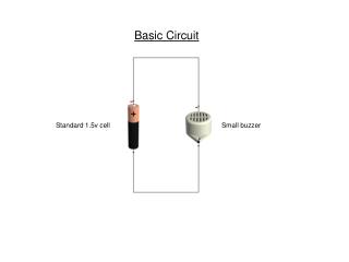
Current Simple DC Circuit
Current Metaphor Increasing V is compared to ? Increasing R is compared to ?
Ohm’s Law for using with a resistor only V = IR Voltage (Volts) = current (Amperes) x resistance (Ohms) 2A 2Ω x+4 volts x volts Note: Electric wire has a resistance of 0 ohms
Electric Current 1A 1A 1A Every point in the circuit has current = 1A
Electric Voltage x + 1 Volts x Volts
Ground Ground = reference point always have voltage = 0 volts 1 Volts 0 Volts
Electric Voltage (2) 1 Volts 0 Volts 0 Volts
Electric Voltage (3) 1 Volts 1 Volts 0 Volts 1 Volts
Negative Voltage and Current + 2 volts - - -2 volts + Same as 1 A -1 A Same as
Power Symbol P has a unit of Watt P = VI I + V - Absorb power I - V + Generate power
Passive Sign Convention Absorb power: Power has a sign + Generate power: Power has a sign-
2.5mA Example DC source generates power = 10V * -2.5mA = - 25mW Resistor absorbs power = 10V * 2.5mA = 25mW Note: Resistors always absorb power but DC source can either generate or absorb power
Direction of Voltage & Current on Resistors or + - - + Resistor always absorb power. Therefore, it always have current flow through it from high voltage pin to low voltage pin.