Download
1 / 18
220 likes | 486 Views
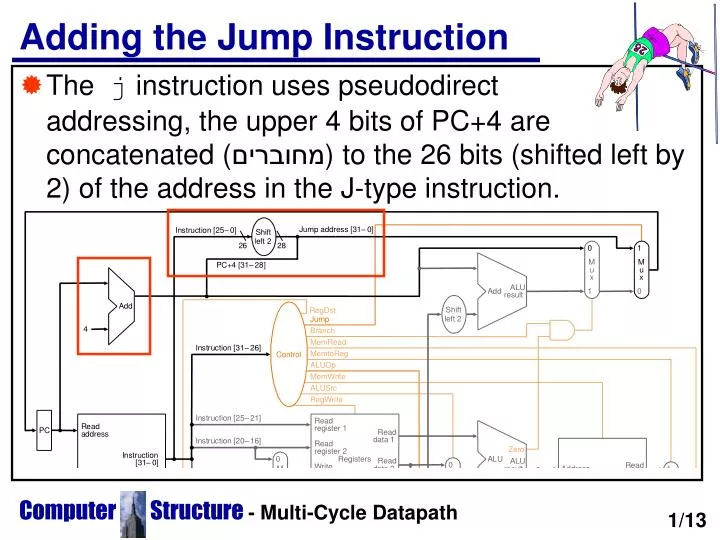
Adding the Jump Instruction. The j instruction uses pseudodirect addressing, the upper 4 bits of PC+4 are concatenated ( מחוברים ) to the 26 bits (shifted left by 2) of the address in the J-type instruction. 1/13. Operation of the Datapath.

E N D
Adding the Jump Instruction • The j instruction uses pseudodirect addressing, the upper 4 bits of PC+4 are concatenated (מחוברים) to the 26 bits (shifted left by 2) of the address in the J-type instruction. Computer Structure- Multi-Cycle Datapath 1/13
Operation of the Datapath • Let's see the stages of execution of a R-type instruction add $t1,$t2,$t3: 1. An instruction is fetched from memory, the PC is incremented 2. Two registers $t2 and $t3 are read from the register file. 3. The ALU operates on the data read from the register file. 4. The results of the ALU is written into the register $t3. • This doesn't really happen in 4 steps because the implementation is combinational, but at the end of the clock cycle the result is written into the destination register. Computer Structure- Multi-Cycle Datapath 2/13
Let's see the stages of execution of branch instruction beq $t1,$t2,L1: 1. An instruction is fetched from memory, the PC is incremented 2. Two registers $t1 and $t2 are read from the register file. 2a. The branch ALU computes the sum of the PC and the sign-extended L1. 3. The ALU operates on the data read from the register file. 4. The output of the ALU decides if the PC is PC+4 or PC+L1. • Let's look at lw $t1,offset($t2) 1. An instruction is fetched from memory, the PC is incremented 2. The register $t2 is read from the register file. 3. The ALU computes the sum of $t2 and the sign-extended offset. 4. The sum from the ALU is used as the address for the data memory. 5. The data from memory is written into register $t1. • Let's look at j L2 1. An instruction is fetched from memory, the PC is incremented 2. The PC is set to the L2 label (concatenated with the 4 MSBs of the PC). Computer Structure- Multi-Cycle Datapath
Goal: Design a Multi-Cycle Datapath • The datapath presented completes in a single machine cycle. Every instruction completes in the same time. • This is inefficient as the cycle time must be that of the longest instruction executed. • We will assume the following delays for each unit: • Memory: 2 ns (nanoseconds) • ALU: 2 ns • Register File: 1ns • Wires, MUXs, Sign-extend, PC ...: 0ns Computer Structure- Multi-Cycle Datapath 3/13
Performance of Single-Cycle Machines • Which implementation is faster? 1. A clock cycle of fixed length.2. A clock cycle of varying length. • Lets look at the time needed by each instruction:Inst. Fetch Reg. Rd ALU op Memory Reg. Wr TotalR-Type 2 1 2 0 1 6nsLoad 2 1 2 2 1 8nsStore 2 1 2 2 7nsBranch 2 1 2 5nsJump 2 2ns • In a fixed clock datapath the clock cycle is 8ns. Computer Structure- Multi-Cycle Datapath 4/13
Fixed vs. Variable Cycle Performance • A program has the following instruction mix: 24% loads, 12% stores, 44% R-type, 18% branches, 2% jumps. • CPU execution time = Instruction count * Cycle time • Fixed Cycle ET (100 inst.) = 100*8ns = 800ns • Variable cycle ET (100 inst.) = 8*24 + 7*12 + 6*44 + 5*18 + 2*2 = 634 ns • The variable clock is better but much harder to implement. • Single cycle is only 634/800 = 79% slower. Why not use it? Computer Structure- Multi-Cycle Datapath 5/13
For the former instruction mix a fixed cycle clock might do. But what about multiplication, division, floating point operations. A division instruction can take 40ns. It is obvious that a better solution is needed. • If we brake each instruction into several steps, we can use these steps to build a multicycle implementation. Each step takes 1 cycle. Instructions such as jumps and branches can complete in less cycles. • Another advantage is that the multicycle implementation allows a functional unit to be used more than once in each instruction as long as it is used on different clock cycles. Computer Structure- Multi-Cycle Datapath
A Multicycle Implementation • We now have only a single memory unit and a single ALU. In addition we need registers to hold the output of each stage. Computer Structure- Multi-Cycle Datapath 6/13
We have now added several new registers(which are transparent to the programmer, they can’t be accessed by software) and some new MUXs: • Instruction Register (IR) - the instruction fetched • Memory Data Register (MDR) - data read from memory • A, B - registers read from the register file • ALUOut - result of ALU operation • The new MUXs added are: • An additional MUX to the 1st ALU input, chooses between the A register and the PC. • The MUX on the 2nd ALU input is changed from a 2-way to a 4-way MUX. The additional inputs are the constant 4 (used to increment the PC) and the sign-extended and shifted offset field (used in beq). • There are 3 possible sources for the PC value: 1. The output of the ALU which is PC+4; 2. The register ALUOut which is the address of the computed branch target; 3. The lower 26 bits of the IR shifted left by 2, concatenated with the 4 upper bits of the PC. Computer Structure- Multi-Cycle Datapath
Multicycle Diagram Computer Structure- Multi-Cycle Datapath 7/13
The Instruction Execution Stages (1,2) 1. Instruction Fetch (IF) - Fetch the instruction from memory and compute the address of the next sequential address:IR = Memory[PC]; PC= PC + 4; 2. Instruction Decode (ID) and register fetch - get the registers from the register file and compute the potential branch address (even if it isn't needed in the future):A = Reg[IR[25-21]];B = Reg[IR[20-16]];ALUOut = PC + (sign-extended(IR[15-0])<<2); Computer Structure- Multi-Cycle Datapath 8/13
The Instruction Execution Stages (3) 3. Execution (EX), Memory address computation or branch completion - In this stage the operation is determined by the the instruction class: A. Memory reference:ALUOut = A + sign-extended(IR[15-0]);B. R-type: ALUOut = A op B;C. Branch:if (A == B) PC = ALUOut;D. Jump:PC = PC[31-28] cat (IR[25-0]<<2) Computer Structure- Multi-Cycle Datapath 9/13
The Instruction Execution Stages (4,5) 4. Memory access (Mem) or R-type completion - During this step the load/store instruction accesses memory or the AL instruction write its results.A. Memory reference:MDR = Memory[ALUOut]; (load)Memory[ALUOut] = B; (store)B. R-type:Reg[IR[15-11]] = ALUOut; 5. Memory read completion ( Write Back - WB ) step - The load completes by writing the value from memory into a register.Reg[IR[20-16]]= MDR; Computer Structure- Multi-Cycle Datapath 10/13
Cycles Per Instruction (CPI) • The CPIof a program defines how many cycles an average instruction takes. • Assuming an instruction mix of: 22% loads, 11% stores, 49% R-type, 16% branch, 2% jumps • Clock cycles for each instruction format is: Loads: 5; Stores: 4; R-type: 4; Branches: 3; Jumps: 3 • CPI = 0.22*5 + (0.11 + 0.49)*4 + (0.16 + 0.02)*3 = 4.04 • This is better than a CPI of 5.00 if all instructions took the same number of cycles. Computer Structure- Multi-Cycle Datapath 11/13
One of the most hardest parts of control is implementing exceptions and interrupts, events other than branches and jumps which change the normal flow of instruction execution. • An exception is an unexpected event that happens during program execution such as an arithmetic overflow or an illegal instruction (which are the only 2 in our design). • An interrupt is an event that is external to the processor, such as requests by I/O devices. • When an exception occurs the machine must save the address of the offending instruction in the exception program counter (EPC), and then transfer execution to the OS. The OS might service the exception and return control to the program or terminate execution. • The OS uses vectored interrupts in order to process the interrupts. In a vectored interrupt the address to which control is transferred is determined by the exception cause. The OS knows the cause of the exception by the address that is jumped to. • In MIPS all exceptions jump to the same routine. there the OS reads a register called the Cause registerand decides how to process the interrupt depending on the value in the cause register. Computer Structure- Multi-Cycle Datapath
Exceptions • When an exception occurs the cause is written into the Cause Register. • The Cause Register holds 0 for an undefined instruction and 1 for an arithmetic overflow. • The EPC holds the address of the instruction which caused the exception, the OS might need to return to the program. • 2 control signals are needed to write to the EPC and cause registers (EPCWrite and CauseWrite). • A signal is needed to set the LSB of the Cause register (IntCause). • IntCause is defined by the control if it can't decode the instruction or if the ALU signals an overflow. The next PC MUX now has 4 inputs, the exception handler addr is added Computer Structure- Multi-Cycle Datapath 12/13
Datapath with Exceptions Computer Structure- Multi-Cycle Datapath 13/13