Download

1 / 55
600 likes | 647 Views
FX2N(C)/FX1N/FX0N CANopen Communicationmodul. FX2N- 32CAN: CiA: DS-301/3.00. connectivity. CANopen modul: FX2N- 32CAN. The FX2N-32CAN can be used to connect a Mitsubishi FX2N/FX1N PLC to an existing CANopen network. CANopen is an internationally accepted

E N D
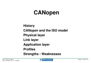
FX2N(C)/FX1N/FX0N CANopen Communicationmodul FX2N- 32CAN: CiA: DS-301/3.00
connectivity CANopen modul: FX2N- 32CAN • The FX2N-32CAN can be used to • connect a Mitsubishi FX2N/FX1N PLC • to an existing CANopen network. • CANopen is an internationally accepted • network standard for industrial automation. • It is promoted by the Germany based user • organization CAN in Automation (CiA). • For further details please refer to • www.can-cia.de .
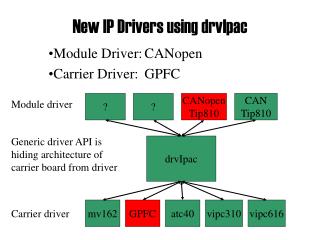
Hey, I CAN do it with FX !!! Features of the FX2N- 32CAN Module Project based Solution • Communication via CANopen-Protocol • A maximum of 120 words can be send and received as Process Data Object (PDO) data. • Occupied I/O-signals: 8 • Baudrate max. 1 Mbit/s • max. Nodes: 127 • PLC-Communication via FROM/TO- instruction • Art. No.: 141179 Project price € 325
Cable and Connector Specification • Cable specification is according to ISO11898/1993. • Recommended is a shielded 2 x 2 twisted pair cable with an impedance of about 120 Ohm Example: UNITRONIC BUS LD 2 x 2 x 0.22 from company Lapp Kabel, www.lappkabel.de • The bus line should be terminated on both ends by connectors that contain 120 Ohm termination resistors. Recommended is a connector which was designed to be used with CANopen networks. Example: ERbic series from company ERNI, www.erni.com
Pin Signal Description 1 - 2 CAN_L CAN-L bus line dominant low 3 CAN_GND CAN Ground 4 - 5 - 6 - 7 CAN_H CAN_H bus line dominant high 8 - 9 - 9-pin D-Sub: DIN 41652 FX2N-32CAN: CiA DS-102, Version 2
Supported CANopen Features • Network Management Service (NMT): Master/Slave • No. of Tx_PDOs (Transmit Process Data Objects): variable (0~30) • No. of Rx_PDOs (Receive Process Data Objects): variable (0~30) • Variable PDO-Mapping: Yes • Emergency Messages: Yes • Node Guarding: Yes • No. of SDOs (Service Data Objects): 2 (1 Tx / 1 Rx)
Supported CANopen Features • Simple mode for connection to other FX2N/FX1N PLCs • Integrated Command Interface (configuration of smaller networks by PLC program) • Command Interface Functionality: • SDO read request, SDO write request • LAYER2 message write command • Remote Transmission Request of local PDO • Definition / change of PDO mapping / binding over the network by FROM/TO • Setup of Node Guarding Parameter Data • Read Node Guarding Status • Reset Guarding Status Latch • Read Emergency Message Buffer • Clear Emergency Message Buffer
Extended BFM Structure (BFM32 ~ BFM32767) The Module Command Interface (CIF) offers the possibility to send commands directly to the CANopen module.
Example: FX2N-32CAN <-> FR-A5NCO FX2N-32CAN Station #1 FR-A5NCO Station #2 Power supply 0V +24V 120 Ohm 120 Ohm 1. CAN_GND 2. CAN_L 3. (CAN_SHLD) 4. CAN_H 5. (CAN_V+) 2. CAN_L 3. CAN_GND 7. CAN_H
Example: Set Baudrate, Station no. and WDT FX2N-32CAN Station #1 FR-A5NCO Station #2 BFM# Write (TO) Pr. No. Function Default Setting BFM24 Baudrate Value 345 CanOpen Address Startup Data 41023 (A03FH) 10kBaud 10 20kBaud 20 346 CanOpen Baudrate Startup Data 20612 (5064H) 50kBaud 50 125kBaud 125 250kBaud 250 b15 b5 b4 b0 500kBaud 500 P345 not used Node Address (1-100) 800kBaud 800 1MBaud 1000 IF P345=100 the node no. is taken from dip switches. Otherwise the node no. is the one set in P345 (1-99). BFM26 TO/FROM WatchDogTimer 20 = 200ms (default) 0 = OFF b15 b5 b4 b0 P346 not used Baudrate BFM27 1-127 (127default) 1 = 1MBaud, 2=500kBaud, 3 = 250kBaud, 4 = 125kBaud, 7 = 50kBaud, 8 = 20 kBaud
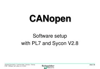
Example: Set Baudrate, Station no. and WDT FX2N-32CAN Station #1 GX IEC Developer BFM# Write (TO) BFM24 Baudrate Value 10kBaud 10 20kBaud 20 50kBaud 50 125kBaud 125 250kBaud 250 500kBaud 500 800kBaud 800 1MBaud 1000 BFM26 TO/FROM WatchDogTimer 20 = 200ms (default) 0 = OFF BFM27 1-127 (127default)
Used Functions in this Example FX2N-32CAN FR-A5NCO Transmit: txPDO1 BFM0 (Inverter command) BFM1 (Set frequency) Receive: rxPDO1 BFM0 (Status) BFM1 (Speed) BFM2 (Current) BFM3 (Alarm) Receive: rxPDO1 Byte 0,1 (Inverter command) Byte 2,3 (Set frequency) Transmit: txPDO1 Byte 0,1 (Status) Byte 2,3 (Speed) Byte 4,5 (Current) Byte 6,7 (Alarm) SDO: Configure binding PDOs NTM: Set CanOpen bus to operational state
Receive rxPDOs (default) Node #1 FX2N-32CAN Node #2 FR-A5NCO rxPDO (Process Data Object) default COB-ID (Can OBject Identifier): 200hex + Node ID 300hex + Node ID 400hex + Node ID 500hex + Node ID default data Objects: vendor/profile specific ----------------------------------------------------------- rxPDO1: COB-ID: 202hex data: InverterCommand Invertersetspeed (Hz) not defined not defined rxPDO2: COB-ID: 302hex data: not defined rxPDO3: COB-ID: 402hex data: not defined rxPDO4: COB-ID: 502hex data: not defined rxPDO (Process Data Object) default COB-ID (Can OBject Identifier): 200hex + Node ID 300hex + Node ID 400hex + Node ID 500hex + Node ID default data Objects: vendor/profile specific --------------------------------------------------- rxPDO1: COB-ID: 201hex data: BFM0 BFM1 BFM2 BFM3 rxPDO2: COB-ID: 301hex data: BFM4-BFM7 rxPDO3: COB-ID: 401hex data: BFM8-BFM11 rxPDO4: COB-ID: 501hex data: BFM12-BFM15
Transmit txPDOs (default) Node #1 FX2N-32CAN Node #2 FR-A5NCO txPDO (Process Data Object) default COB-ID (Can OBject Identifier): 180hex + Node ID 280hex + Node ID 380hex + Node ID 480hex + Node ID default data Objects: vendor/profile specific ------------------------------------------------------------- txPDO1: COB-ID: 181hex data: BFM0 BFM1 BFM2 BFM3 txPDO2: COB-ID: 281hex data: BFM4-BFM7 txPDO3: COB-ID: 381hex data: BFM8-BFM11 txPDO4: COB-ID: 481hex data: BFM12-BFM15 txPDO (Process Data Object) default COB-ID (Can OBject Identifier): 180hex + Node ID 280hex + Node ID 380hex + Node ID 480hex + Node ID default data Objects: vendor/profile specific ------------------------------------------------------------- txPDO1: COB-ID: 182hex data: Inverter status Inverter actualSpeed (Hz) Inverter current Alarms txPDO2: COB-ID: 282hex data: not defined txPDO3: COB-ID: 382hex data: not defined txPDO4: COB-ID: 482hex data: not defined
Message with COB-ID 181hex 202hex 302hex 402hex 502hex FX2N-32CAN transmit PDO1 to FR-A5NCO(both nodes in default setting) Node #2 FR-A5NCO Node #1 FX2N-32CAN txPDO1: COB-ID: 181hex data: BFM0-BFM3 txPDO2: COB-ID: 281hex data: BFM4-BFM7 txPDO3: COB-ID: 381hex data: BFM8-BFM11 txPDO4: COB-ID: 481hex data: BFM12-BFM15 --------------------------------------------------------------------- rxPDO1: COB-ID: 201hex data: BFM0-BFM3 rxPDO2: COB-ID: 301hex data: BFM0-BFM3 rxPDO3: COB-ID: 401hex data: BFM0-BFM3 rxPDO4: COB-ID: 501hex data: BFM0-BFM3 txPDO1: COB-ID: 182hex data: status, speed,current,alarm txPDO2: COB-ID: 282hex data: empty txPDO3: COB-ID: 382hex data: empty txPDO4: COB-ID: 482hex data: empty --------------------------------------------------------------------- rxPDO1: COB-ID: 202hex data: command, set Speed (Hz) rxPDO2: COB-ID: 302hex data: empty rxPDO3: COB-ID: 402hex data: empty rxPDO4: COB-ID: 502hex data: empty --> --> --> --> <-- <-- <-- <-- <-- <-- <-- <-- --> --> --> --> CANopen BUS This means that the message with the COB-ID 181hex is not (received) evaluated by node 2
181hex By a configuration tool or a PLC program the rxPDO COB-ID is changed to 181hex / param. index 1400H FX2N-32CAN transmit PDO1 to FR-A5NCO (“binding” of the PDOs) Node #2 FR-A5NCO Node #1 FX2N-32CAN txPDO1: COB-ID: 181hex data: BFM0-BFM3 txPDO2: COB-ID: 281hex data: BFM4-BFM7 txPDO3: COB-ID: 381hex data: BFM8-BFM11 txPDO4: COB-ID: 481hex data: BFM12-BFM15 --------------------------------------------------------------------- rxPDO1: COB-ID: 201hex data: BFM0-BFM3 rxPDO2: COB-ID: 301hex data: BFM0-BFM3 rxPDO3: COB-ID: 401hex data: BFM0-BFM3 rxPDO4: COB-ID: 501hex data: BFM0-BFM3 txPDO1: COB-ID: 182hex data: status, speed,current,alarm txPDO2: COB-ID: 282hex data: empty txPDO3: COB-ID: 382hex data: empty txPDO4: COB-ID: 482hex data: empty --------------------------------------------------------------------- rxPDO1: COB-ID: 202hex data: command, set Speed (Hz) rxPDO2: COB-ID: 302hex data: empty rxPDO3: COB-ID: 402hex data: empty rxPDO4: COB-ID: 502hex data: empty --> --> --> --> <-- <-- <-- <-- <-- <-- <-- <-- --> --> --> --> CANopen BUS To build this ‘data connection’ between node #1 and node #2 make the COB-ID which is used to transmit the data of txPDO1 by node #1 the same as the COB-ID which is received and stored to rxPDO1 by node #2.
Message with COB-ID 181hex FX2N-32CAN transmit PDO1 to FR-A5NCO (“binding” established) Node #2 FR-A5NCO Node #1 FX2N-32CAN txPDO1: COB-ID: 181hex data: BFM0-BFM3 txPDO2: COB-ID: 281hex data: BFM4-BFM7 txPDO3: COB-ID: 381hex data: BFM8-BFM11 txPDO4: COB-ID: 481hex data: BFM12-BFM15 --------------------------------------------------------------------- rxPDO1: COB-ID: 201hex data: BFM0-BFM3 rxPDO2: COB-ID: 301hex data: BFM0-BFM3 rxPDO3: COB-ID: 401hex data: BFM0-BFM3 rxPDO4: COB-ID: 501hex data: BFM0-BFM3 txPDO1: COB-ID: 182hex data: status, speed,current,alarm txPDO2: COB-ID: 282hex data: empty txPDO3: COB-ID: 382hex data: empty txPDO4: COB-ID: 482hex data: empty --------------------------------------------------------------------- rxPDO1: COB-ID: 181hex data: command, set speed (Hz) rxPDO2: COB-ID: 302hex data: empty rxPDO3: COB-ID: 402hex data: empty rxPDO4: COB-ID: 502hex data: empty --> --> --> --> <-- <-- <-- <-- <-- <-- <-- <-- --> --> --> --> CANopen BUS Now the rxPDO1 of node 2, will receive the data of node 1 BFM0-BFM3.
Message with COB-ID 182hex 201hex 301hex 401hex 501hex FR-A5NCO transmit PDO1 to FX2N-32CAN(both nodes in default setting) Node #2 FR-A5NCO Node #1 FX2N-32CAN txPDO1: COB-ID: 182hex data: status, speed,current,alarm txPDO2: COB-ID: 282hex data: empty txPDO3: COB-ID: 382hex data: empty txPDO4: COB-ID: 482hex data: empty --------------------------------------------------------------------- rxPDO1: COB-ID: 181hex data: command, set Speed (Hz) rxPDO2: COB-ID: 302hex data: empty rxPDO3: COB-ID: 402hex data: empty rxPDO4: COB-ID: 502hex data: empty txPDO1: COB-ID: 181hex data: BFM0-BFM3 txPDO2: COB-ID: 281hex data: BFM4-BFM7 txPDO3: COB-ID: 381hex data: BFM8-BFM11 txPDO4: COB-ID: 481hex data: BFM12-BFM15 --------------------------------------------------------------------- rxPDO1: COB-ID: 201hex data: BFM0-BFM3 rxPDO2: COB-ID: 301hex data: BFM0-BFM3 rxPDO3: COB-ID: 401hex data: BFM0-BFM3 rxPDO4: COB-ID: 501hex data: BFM0-BFM3 --> --> --> --> <-- <-- <-- <-- <-- <-- <-- <-- --> --> --> --> CANopen BUS This means that the message with the COB-ID 182hex is not (received) evaluated by node 1
182hex By a configuration tool or a PLC program the rxPDO COB-ID is changed to 182hex / param. index 1400H FR-A5NCO transmit PDO1 to FX2N-32CAN (“binding” of the PDOs) Node #2 FR-A5NCO Node #1 FX2N-32CAN txPDO1: COB-ID: 181hex data: BFM0-BFM3 txPDO2: COB-ID: 281hex data: BFM4-BFM7 txPDO3: COB-ID: 381hex data: BFM8-BFM11 txPDO4: COB-ID: 481hex data: BFM12-BFM15 --------------------------------------------------------------------- rxPDO1: COB-ID: 201hex data: BFM0-BFM3 rxPDO2: COB-ID: 301hex data: BFM0-BFM3 rxPDO3: COB-ID: 401hex data: BFM0-BFM3 rxPDO4: COB-ID: 501hex data: BFM0-BFM3 txPDO1: COB-ID: 182hex data: status, speed,current,alarm txPDO2: COB-ID: 282hex data: empty txPDO3: COB-ID: 382hex data: empty txPDO4: COB-ID: 482hex data: empty --------------------------------------------------------------------- rxPDO1: COB-ID: 181hex data: command, set Speed (Hz) rxPDO2: COB-ID: 302hex data: empty rxPDO3: COB-ID: 402hex data: empty rxPDO4: COB-ID: 502hex data: empty --> --> --> --> <-- <-- <-- <-- <-- <-- <-- <-- --> --> --> --> CANopen BUS To build this ‘data connection’ between node #2 and node #1 make the COB-ID which is used to transmit the data of txPDO1 by node #2 the same as the COB-ID which is received and stored to rxPDO1 by node #1.
Message with COB-ID 182hex FR-A5NCO transmit PDO1 to FX2N-32CAN(“binding” established) Node #2 FR-A5NCO Node #1 FX2N-32CAN txPDO1: COB-ID: 181hex data: BFM0-BFM3 txPDO2: COB-ID: 281hex data: BFM4-BFM7 txPDO3: COB-ID: 381hex data: BFM8-BFM11 txPDO4: COB-ID: 481hex data: BFM12-BFM15 --------------------------------------------------------------------- rxPDO1: COB-ID: 182hex data: BFM0-BFM3 rxPDO2: COB-ID: 301hex data: BFM0-BFM3 rxPDO3: COB-ID: 401hex data: BFM0-BFM3 rxPDO4: COB-ID: 501hex data: BFM0-BFM3 txPDO1: COB-ID: 182hex data: status, speed,current,alarm txPDO2: COB-ID: 282hex data: empty txPDO3: COB-ID: 382hex data: empty txPDO4: COB-ID: 482hex data: empty --------------------------------------------------------------------- rxPDO1: COB-ID: 181hex data: command, set Speed (Hz) rxPDO2: COB-ID: 302hex data: empty rxPDO3: COB-ID: 402hex data: empty rxPDO4: COB-ID: 502hex data: empty --> --> --> --> <-- <-- <-- <-- <-- <-- <-- <-- --> --> --> --> CANopen BUS Now the rxPDO1 of node 1, will receive the data of node 2 status,speed,current and alarm
Object 1400h - 15FFh : Receive PDO Communication Parameter(for details see DS301 page 9-83)
Object 1400h: Receive PDO1 Communication Parameter (Sub-Index: 0h) Node #2 (FR-A5NCO) The receive PDO1 communication parameter from the FR-A5NCO contains a number of 5 valid Sub-Index within the communication record !
Object 1400h - 15FFh: Receive PDO Communication Parameter (Sub-Index: 1h)
40000181 01000000 00000000 00000001 10000001 b31.........................................................b0 Object 1400h:Change receive PDO1 202h to 181 (Sub-Index 1h) Node #2 (FR-A5NCO) RTR FR-A5NCO FX2N-32CAN
Object 1400h: Receive PDO Communication Parameter (Sub-Index: 2h) Transmission type 255 means event triggert. RPDOs with that type, trigger the update of the mapped data with the reception.
Object 1400h - 15FFh: Receive PDO Communication Parameter Sub-index 3h contains the inhibit time. This time is a minimum interval for PDO transmission. The value is defined as multiple of 100ms. Sub-index 4h is reserved. In mode 254/255 additionally an event time can be used for TPDO. This Index is not used for receive rxPDOs
40000181 01000000 00000000 00000001 10000001 b31.........................................................b0 Changing rxPDO1 COB-ID from Node2 (FR-A5NCO) Module Command Interface (CIF) BFM# Read (FROM) Write (TO) BFM1000 Result (read 0005/write 0003) 3 Command (read 0004/write 0002) 2 BFM1001 Node address 2 Node address 2 BFM1002 Index 1400h Index 1400h BFM1003 Sub-Index 1 Sub-Index 1 BFM1004 Data lenght 0 Data lenght 4 (Bytes) BFM1005 Result Data 0 Command parameter data 0181h BFM1006 Result Data 0 Command parameter data 4000h Changing: rxPDO1 (202h) -> rxPDO1 (181h) For details see DS301 page 9-83
00000182 00000000 00000000 00000001 10000010 b31.........................................................b0 Changing rxPDO1 COB-ID from Node1 (FX2N-32CAN) Module Command Interface (CIF) BFM# Read (FROM) Write (TO) BFM1000 Result (read 0005/write 0003) 3 Command (read 0004/write 0002) 2 BFM1001 Node address 1 Node address 1 BFM1002 Index 1400h Index 1400h BFM1003 Sub-Index 1 Sub-Index 1 BFM1004 Data lenght 0 Data lenght 4 (Bytes) BFM1005 Result Data 0 Command parameter data 0182h BFM1006 Result Data 0 Command parameter data 0000h Changing: rxPDO1 (201h) -> rxPDO1 (182h) For details see DS301 page 9-83
Set the CanOpen Bus to Operational State Module Command Interface (CIF) BFM# Read (FROM) Write (TO) BFM1000 Result (read 0005/write 0003) 3 Command (read 0004/write 0002) 2 BFM1001 Node address 0 Node address 0 BFM1002 Index 1F82h Index 1F82h BFM1003 Sub-Index 80h Sub-Index 80h BFM1004 Data lenght 0 Data lenght 1 (Bytes) BFM1005 Result Data 0 Command parameter data 5 Operational state: Node address 0 means all nodes For details see DSP302 page 21
Data Exchange between FX2N-PLC <->FX2N-32CAN BFM# Read (FROM) Write (TO) BFM0 Receive Data rxPDO1 (Byte1,Byte0) Transmit Data txPDO1 (Byte1,Byte0) BFM1 Receive Data rxPDO1 (Byte3,Byte2) Transmit Data txPDO1 (Byte3,Byte2) BFM2 Receive Data rxPDO1 (Byte5,Byte4) Transmit Data txPDO1 (Byte5,Byte4) BFM3 Receive Data rxPDO1 (Byte7,Byte6) Transmit Data txPDO1 (Byte7,Byte6) BFM20 Data exchange status bit Data exchange refresh bit To ensure that the FX2N-32CAN module can handle the PDO data in a consistent way, it is absolutely necessary to write a ”1” to this BFM20
Default PDOs FR-A5NCO Receive PDO1 (181h) Inverter Command Transmit PDO1 (182h) Inverter Status Additional PDOs: not mapped receive PDO2-PDO4 / transmit PDO2-PDO4
Start Forward Inverter(STF) with 50,00Hz Inverter Command
Define txPDO1 from FR-A5NCO as „timer event“ Module Command Interface (CIF) BFM# Read (FROM) Write (TO) BFM1000 Result (read 0005/write 0003) 3 Command (read 0004/write 0002) 2 BFM1001 Node address 2 Node address 2 BFM1002 Index 1800h Index 1800h BFM1003 Sub-Index 5h Sub-Index 5h BFM1004 Data lenght 0 Data lenght 2 (Bytes) BFM1005 Result Data 0 Command parameter data 100 The FR-A5NCO option card will send the transmit data txPDO1 automatically every 100ms to the FX2N-32CAN (BFM0,BFM1,BFM2,BFM3) For details see DS301 page 9-88
Monitor the running Inverter Inverter Status
Save configuration of FX2N-32CAN (FR-A5NCO are saved automatic) Module Command Interface (CIF) BFM# Read (FROM) Write (TO) BFM1000 Result (read 0005/write 0003) 3 Command (read 0004/write 0002) 2 BFM1001 Node address 1 Node address 1 BFM1002 Index 1010h Index 1010h BFM1003 Sub-Index 1 Sub-Index 1 BFM1004 Data lenght 0 Data lenght 4 (Bytes) BFM1005 Result Data 0 Command parameter data 6173h BFM1006 Result Data 0 Command parameter data 6576h This object supports the saving of parameters in non volatile memory. For details see DS301 page 9-70
Save configuration of FX2N-32CAN (FR-A5NCO are saved automatic)
Load default configuration of FX2N-32CAN Module Command Interface (CIF) BFM# Read (FROM) Write (TO) BFM1000 Result (read 0005/write 0003) 3 Command (read 0004/write 0002) 2 BFM1001 Node address 1 Node address 1 BFM1002 Index 1011h Index 1011h BFM1003 Sub-Index 1 Sub-Index 1 BFM1004 Data lenght 0 Data lenght 4 (Bytes) BFM1005 Result Data 0 Command parameter data 6F6Ch BFM1006 Result Data 0 Command parameter data 6461h With this object the default values of parameters according to the communication or device profile are restored. For details see DS301 page 9-72
Node Guarding: Disconnect cable from FR-A5NCO • Node Guarding Protocol is supported, according to CiA specifications • Object at index 100CH, sub-index 0H defines the guard time (1ms) • and object at index 100DH, sub-index 0H defines the retry factor • When the node doesn’t receive the polling from the master • it sends an emergency message; the motor can be stopped, • left free to rotate, …, according to object 6007H/0H value Object 6007H 0: No action 2: Device control command ”disable_voltage” 3: Device control command ”quick_stop” For details see DS301 page 9-69 / FR-A5NCO manual page 31
Node Guarding Node 2 (FR-A5NCO):Object 100C „guard time” Module Command Interface (CIF) BFM# Read (FROM) Write (TO) BFM1000 Result (read 0005/write 0003) 3 Command (read 0004/write 0002) 2 BFM1001 Node address 2 Node address 2 BFM1002 Index 100Ch Index 100Ch BFM1003 Sub-Index 0 Sub-Index 0 BFM1004 Data lenght 0 Data lenght 2 (Bytes) BFM1005 Result Data 0 Command parameter data 100 The guard time will set to 100ms For details see DS302 page 9-69
Node Guarding Node 2 (FR-A5NCO):Object 100D „life time factor” Module Command Interface (CIF) BFM# Read (FROM) Write (TO) BFM1000 Result (read 0005/write 0003) 3 Command (read 0004/write 0002) 2 BFM1001 Node address 2 Node address 2 BFM1002 Index 100Dh Index 100Dh BFM1003 Sub-Index 0 Sub-Index 0 BFM1004 Data lenght 0 Data lenght 1 (Bytes) BFM1005 Result Data 0 Command parameter data 4 After 4 retrys the FR-A5NCO will “quick stop” the inverter if the Object 6007 is set to 3 For details see DSP302 page 16
Node Guarding Node 2 (FR-A5NCO):Object 100D „life time factor ”
Node Guarding Node 2 (FR-A5NCO):Object 6007 „abort connection” Module Command Interface (CIF) BFM# Read (FROM) Write (TO) BFM1000 Result (read 0005/write 0003) 3 Command (read 0004/write 0002) 2 BFM1001 Node address 2 Node address 2 BFM1002 Index 6007h Index 6007h BFM1003 Sub-Index 0 Sub-Index 0 BFM1004 Data lenght 0 Data lenght 1 (Bytes) BFM1005 Result Data 0 Command parameter data 3 After 4 retrys the FR-A5NCO will “quick stop” the inverter if the Object 6007 is set to 3 For details see FR-A5NCO manual page 35