Download
1 / 15
150 likes | 322 Views
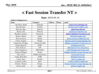
< Fast Session Transfer NT >. May 2010. Date: 2010-05-18. Slide 1. Slide 2. Slide 3. Slide 4. May 2010. Slide 5. Slide 5. Naveen Kakani, Nokia et., al. Proposal overview.

E N D
< Fast Session Transfer NT > May 2010 Date: 2010-05-18 Slide 1 Naveen Kakani, Nokia et., al
Slide 2 Naveen Kakani, Nokia et., al
Slide 3 Naveen Kakani, Nokia et., al
Slide 4 Naveen Kakani, Nokia et., al
May 2010 Slide 5 Slide 5 Naveen Kakani, Nokia et., al
Proposal overview • This presentation is part and is in support of the complete proposal described in 802.11-10/432r2 (slides) and 802.11-10/433r2 (text) that: • Supports data transmission rates up to 7 Gbps • Supplements and extends the 802.11 MAC and is backward compatible with the IEEE 802.11 standard • Enables both the low power and the high performance devices, guaranteeing interoperability and communication at gigabit rates • Supports beamforming, enabling robust communication at distances beyond 10 meters • Supports GCMP security and advanced power management • Supports coexistence with other 60GHz systems • Supports fast session transfer among 2.4GHz, 5GHz and 60GHz Slide 6 Naveen Kakani, Nokia et., al
Definition • What is a Session ? • State information kept in a pair of STAs that have an established direct PHY link (i.e., excludes forwarding). • What is Fast Session Transfer ? • The transfer of a session from one physical channel to another channel when the communicating STAs both have matching radios in the frequency band they wish to communicate. Naveen Kakani, Nokia et., al
Scenarios to consider AP/PCP Scenario 1: Either a PCP or AP is one of end-points of the session. Scenario 2: Neither a PCP nor an AP is an end-point of the session but the two STAs involved in the Session are communicating directly It is likely that in both the scenarios the multi-band STA may have multiple MAC addresses or single MAC address and may be communicating simultaneously in the bands that it is capable of operating. Multi-band-capable STA STA1 STA2 Naveen Kakani, Nokia et., al
Example Scenario After FST, STAA and STAB operating in UB STAA and STAB operating in LB • STAA and STAB are associated with AP in 2.4/5GHz and have a Direct Link established • STAA and STAB can be in the vicinity of PCP networks • STAA moves towards STAB and they move the session (that was transported over DLS in 2.4/5GHz) to 60 GHz band Naveen Kakani, Nokia et., al
FST Steps • Step 1 : FST Setup • Parameter and capability negotiation via FST Setup Request and FST Setup Response Frames (7.4.14) • Multiband Element (7.3.2.101) -> Mode of FST Session, STA capabilities in new Band (connection capabilities), Regulatory Information of new Band, Security Parameters, Role of the STA in new Band • Session Transition Element (7.3.2.107) -> Session ID (FSTS ID, assigned by the initiator i.e., FST Request frame transmitter), Session Type (intended type of communication mode in new Band) • Streams being switched : Switching Streams Element (7.3.2.106) • Wakeup Schedule -> advertises the BI during which the STA is awake (7.3.2.94) • Awake Window -> length of Awake Period (7.3.2.100) during CBP period in a BI • Mode of FST Session : • Transparent: Each of the STAs participating in the same FST session has the same MAC addresses in both bands • Non-transparent: At least one of the STA participating in the same FST session has different MAC addresses in each band Naveen Kakani, Nokia et., al
FST Steps continued … Step 1 • Parameter negotiation by : • ADDTS, DELTS, ADDBA, DELBA frames • Multiband Element is included if the frames are transmitted in band other than the band where the session is intended to be transferred • TCLAS Element is included if the FST Session is in non-transparent mode • FST Setup Response with : • Status Code = 55, Pending, no transmission of the FST setup request • Status Code = 39, One or more parameters of the FST Setup Request is invalid and the responder suggests alternative parameters • Status Code = 37, Responder rejects the request. One particular case is that values of the regulatory class and channel number fields within the Multi-band element, if any, received in the FST Setup Request frame is different than the value of the corresponding fields within the Multi-band element, if any, transmitted in the following FST Setup Response Naveen Kakani, Nokia et., al
FST Steps .. continued • Step 2 : FST Switch • Controlled by Status Code in FST Response Frame • FST Response Frame with Status Code = 0 has LLT = 0 -> Switch is immediate • FST Response Frame with Status Code = 0 has LLT > 0 • If all the streams are not being switched it is possible to switch each stream individually (Stream based LLT) or all the streams together (STA based LLT) • An initiator and responder perform the STA-based and stream-based Link Loss Countdown as follows: • STA-based Link Loss Countdown: both initiator and responder remain in the Setup completion state and start a Link Loss countdown timer with an initial value of LLT*32 usec. The Link Loss countdown is reloaded with the value of LLT*32 usec every time that a unicast frame is received from the peer STA of the FST session. • Stream-based Link Loss Countdown: both the initiator and responder start a Link Loss countdown timer with an initial value of LLT*32 usec for each stream identified within the Switching Stream element. The Link Loss countdown for a stream is reloaded with the value of LLT*32 usec every time that a unicast frame for that stream is received from the peer STA of the FST session • The FST transition for the STA, if STA-based, or the stream, if stream-based, from the Setup completion state to the Transition done state occurs immediately after the corresponding Link Loss countdown timer transitions from one to zero within any of the initiator or responder of the FST session • FST Request with “LLT = 0” Naveen Kakani, Nokia et., al
Frame Exchange Sequence - Example FST_Req • Status codes for FST_Res • Pending • Parameters invalid • Reject • Accept FST_Res, Status code “Parameters Invalid” FST_Req FST_Req, Includes New Parameters FST_Res, Status code “Accept” STA2, FST responding STA STA1, FST initiating STA Naveen Kakani, Nokia et., al
FST Switch Confirmation • Successful transmission of FST ACK Request and reception of FST ACK Response in new Band (or) Successful frame exchange • FST ACK request frame is as defined in 7.4.14.5 and FST ACK response frame is as defined in 7.4.14.6 -> includes FSTS ID Naveen Kakani, Nokia et., al
FST Mechanism (11.34) Naveen Kakani, Nokia et., al