Download
1 / 10
100 likes | 291 Views
MULTISALT-CARBON PORTABLE CHEMICAL HEAT PUMP. L.L. Vasiliev D.A.Mishkinis A.A. Antukh A.G. Kulakov L.L. Vasiliev Jr. Luikov Heat & Mass Transfer Institute, Minsk, Belarus. NEW SORBENT COMPLEX COMPOUND ACTIVATED CARBON FIBER “ BUSIFIT ”-METAL CHLORIDE.

E N D
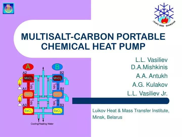
MULTISALT-CARBON PORTABLE CHEMICAL HEAT PUMP L.L. Vasiliev D.A.Mishkinis A.A. Antukh A.G. Kulakov L.L. Vasiliev Jr. Luikov Heat & Mass Transfer Institute, Minsk, Belarus
NEW SORBENT COMPLEX COMPOUND ACTIVATED CARBON FIBER “BUSIFIT”-METAL CHLORIDE The most favourable situation for the RESORPTION HEAT PUMPS is the case, when the presence of a liquid phase is impossible ACF “BUSOFIT” (multiplied in 10000 times) + SALTS : BaCl2 ,NiCl2 ,MnCl2 • ADVANTAGES OF BUSOFIT • AS A SALT HOST MATERIAL • high rate of adsorption and desorption; • uniform surface pore distribution (0.6-1.6 nm); • few macropores (0.1-0.2 mm), 0.5-2 m2/g; • few mesopores with 50 m2/g; • relatively high thermal conductivity SALT = “Busofit” actions as a fast reacting material COMPLEX COMPOUND (multiplied in 10000 times)
Vapor volume Water heat exchanger Sorbent Envelope Fin Vapour entrance Vapour channel Liquid channel TWO REACTORS RESORPTION HEAT PUMP Resorption two reactors heat pump with heat pipe thermal control Reactor with sorbent bed Temperature and Pressure Evolutuin During RHP Reactors heating/cooling
FOUR REACTORS RESORPTION HEAT PUMP Pressure evolution in two branches of reactors Four reactors Resorption Heat Pump Energy balance of the four reactors resorption heat pump
FOUR REACTORS RESORPTION HEAT PUMP Low heat transfer in BaCl2 reactors limited the cold generation. Energy supply, heat and cold generation in four reactors heat pump with different heating mode of high temperature reactors A and B. Temperature field evolution : 1- water entrance to A1, 2 – water cooling in A1, 3 – water heating in B1, 4- water (vapor) heating in A.
SIX REACTORS RESORPTION HEAT PUMP Clapeyron diagram of three- effect resorption system with a temperature lift near 100 0C. Six reactors Resorption Heat Pump
SIX REACTORS RESORPTION HEAT PUMP Three-effect resorption system (BaCl2 , MnCl2, NiCl2). 1 – cold generation in A3 BaCl2 reactor, 2 – heat generation in B3 BaCl2 reactor, 3 – heat flow in the two-phase water system inside of heat exchangers of MnCl2 and NiCl2 reactors, 4 – energy supply by heat pipe HP1 and HP2 electric heating elements Three-effect resorption system, temperature field in: 1 – water entrance. 2 – water in A3 BaCl2 reactor, 3 –water in B3 BaCl2 reactor, 4 – water two-phase flows in MnCl2 and NiCl2 reactors
SIX REACTORS RESORPTION HEAT PUMP Temperature field in the Six Reactors Heat Pump: 1 –water entrance, 2 – cold water in A3 BaCl2 reactor, 3 – warm water in B3 BaCl2 reactor Energy balance of the Six Reactors Heat Pump : 1 – A2 reactor, 2 – A3 reactor, 3 – A1 reactor
SIX REACTORS RESORPTION HEAT PUMP Temperature field on the Heat Pipe-1 and Heat Pipe-2 envelops during the cycle heating/cooling Pressure evolution in the six reactors heat pump (branch A).
CONCLUSIONS • 3 experimental set-ups based on the COMLEX COMPOUNDS NiCl2, MnCl2, BaCl2 – ACTIVE CARBON FIBERn fiber „Busofit“ demonstrated a possibility to have a RESORPTION HEAT PUMP with simultaneous heat (superheated water vapor T = 120 0C – 130 0C) and chilled water production (T = 3 0C – 50C) with COP (without internal and external heat recovery) ~1.2. Heat recovery by the heat pipe thermal regulation and internal mass regeneration between the reactors out of phase could increase this COP up to 1.4-1.5. • The RESORPTION HEAT PUMP with a heat output 1400-1500 W is an autonomous, portable device, allowing the user to apply this system in space, or on the ground (underwater, underground) and to supply, or postpone the heating and cooling capacity and to control the heat and cold output. The device has no moving parts, is noiseless and light. • The pressure control regulation of the heat pump action is the most reliable and simple.