Download
1 / 94
950 likes | 1.09k Views
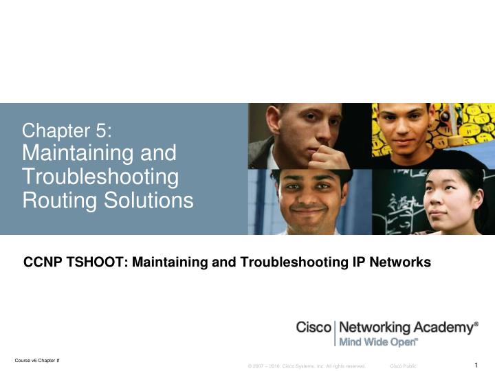
Chapter 5: Maintaining and Troubleshooting Routing Solutions. CCNP TSHOOT: Maintaining and Troubleshooting IP Networks. Chapter 5 Objectives. Diagnose network layer connectivity problems using the IOS command line interface.

E N D
Chapter 5:Maintaining and Troubleshooting Routing Solutions CCNP TSHOOT: Maintaining and Troubleshooting IP Networks
Chapter 5 Objectives • Diagnose network layer connectivity problems using the IOS command line interface. • Diagnose and resolve problems related to the exchange of routing information by the Enhanced Interior Gateway Routing Protocol (EIGRP). • Diagnose and resolve problems related to the exchange of routing information by use of the Open Shortest Path First (OSPF) routing protocol. • Diagnose and resolve problems when redistributing routes. • Diagnose and resolve problems related to the exchange of routing information by use of the Border Gateway Protocol (BGP).
Using IOS Commands to Verify Routing Functions To display the content of the IP routing table use the following commands: • show ip route ip-address: • Displays the best route that matches the address and all associated control plane details. • show ip route network mask: • Searches for exact match for the network and mask specified and displays the entry if found. • Note that if the only route that matches the ip-address argument is the default route, the router will respond with %Network not in table • show ip route network mask longer-prefixes: • Displays prefixes in the routing table that fall within the prefix specified by the network and mask parameters.
Using IOS Commands to Verify Routing Functions – Cont. To display the CEF Forwarding Information Base (FIB) table use the following commands: • show ip cef ip-address: • Searches the FIB instead of the routing table. • Displays only the information that is necessary to forward packet (no routing protocol related information). • show ip cef networkmask: • Displays information from the FIB instead of the routing table (RIB). • show ip cef exact-route sourcedestination: • Displays the exact adjacency used to forward a packet with source and destination IP addresses. • Useful when the routing table and FIB contain two or more equal routes for a particular prefix.
Using IOS Commands to Verify Routing Functions – Cont. To verify the Layer 3 to Layer 2 mappings use the following commands: • show ip arp: • Used to verify the dynamic IP address to Ethernet MAC address mappings that were resolved by ARP. (Use the clear ip arp and clear arp-cache commands to refresh the ARP cache). • show frame-relay map: • Lists all the mappings of next-hop IP addresses on multipoint (sub-) interfaces to the DLCI of the corresponding permanent virtual circuit (PVC). (Use the clear frame inarp command to refresh the IP/DLCI cache). • show adjacency detail: • Displays the full frame header that will be used to encapsulate the packet as well as packet and byte counters for all traffic that was forwarded using a particular adjacency entry. Verify Layer 3 to Layer 2 mappings for the data link protocol used on the egress interface.
Using IOS Commands to Verify Routing Functions – Cont. To clear the FIB and adjacency entries, use the following commands: • IOS version earlier than 12.4(20)T: • clear ip cef epoch: Clears the FIB table • clear adjacency epoch: Clears the adjacency table • clear ip cef epoch full: Clears both the FIB and adjacency • IOS version 12.4(20)T and newer: • clear cef table ipv4: Clears the FIB table • clear adjacency: Clears the adjacency table
IGP Routing Protocol Review Routing protocols consist of the following elements and processes: • Reception of routing information from neighbors • Routing protocol data structures • Route injection or redistribution • Route selection and installation • Transmission of routing information to neighbors
EIGRP Review EIGRP stores its operational data, configured parameters, and statistics in three main data structures: • Interface table: • Lists all interfaces enabled for the processing of EIGRP packets. • Passive interfaces are not listed in this table. • Neighbor table: • Keeps track of active EIGRP neighbors. • Based on reception of hello packets. • Topology table: • Holds routes received from neighboring routers, locally injected, or redistributed into EIGRP. • For each prefix, EIGRP selects the best path (successor route) for the IP routing table. • EIGRP’s best path selection is based on the Diffusing Update Algorithm (DUAL). • Multiple paths with the same metric that satisfy the Feasibility Condition can be selected for installation in the routing table. • Routes with a higher metric are not selected for installation in the routing table, unless unequal cost load balancing has been enabled.
EIGRP Review – Cont. EIGRP uses an incremental update process. • When the adjacency is first established, each router sends a full update to its neighbor router. • All prefixes for which there a successor in the topology table are sent. • After initial exchange, routing updates will only be sent due to changes on the networks. • Changes can be caused by: • Changes in connectivity (such as loss or discovery of a link or neighbor , modification of an interface metric, changes to the split horizon or next-hop modification on an interface, stub routing activation/deactivation) • Addition of new interfaces to EIGRP • Implementation of route summarization • Implementation of route filtering • Implementation of route redistribution
Monitoring EIGRP with show commands • To gather information from the EIGRP data structures use the following show commands: • show ip eigrp interfaces: • Displays the list of interfaces that have been activated for EIGRP processing. • showipeigrpneighbors: • Lists all neighbors that have been discovered by this router on its active EIGRP interfaces. • showipeigrptopology: • Displays the content of the EIGRP topology table. To select a specific entry from the table, the network and mask can be provided as an option to the command.
Monitoring EIGRP with debug Commands To observe the real-time EIGRP information exchange use the following debug commands: • debug ip routing: • Not specific to EIGRP. • Displays changes made to the routing table, such as installation or removal of routes. • Can be useful in diagnosing routing protocol instabilities. • debug eigrp packets: • Displays the transmission and reception of EIGRP packets. • All packets can be displayed, or packets of a particular type, such as hellos, updates, queries, and replies can be selected. • debug ip eigrp: • Displays EIGRP routing events, such as updates, queries, and replies sent to or received from neighbors. • debug ip eigrp neighbor as-numberip-address: • Limits output to information that is associated with the specified neighbor. • debug ip eigrp as-numbernetworkmask: • Limits output to information that is associated with the network specified by the network and mask options.
EIGRP Troubleshooting Example: Packets from BR01 to CR01 Lo0 take wrong path. BRO1# traceroute 10.1.220.1 Type escape sequence to abort. Tracing the route to cro1.mgmt.tshoot.local (10.1.220.1) 1 10.1.163.130 0 msec 0 msec 0 msec 2 10.1.194.5 12 msec 12 msec * BRO1# ping 10.1.194.1 Type escape sequence to abort. Sending 5, 100-byte ICMP Echos to 10.1.194.1, timeout is 2 seconds: !!!!! Success rate is 100 percent (5/5), round-trip min/avg/max = 28/29/32 ms
EIGRP Troubleshooting Example – Cont. BRO1# show ip eigrp topology 10.1.220.1 255.255.255.255 IP-EIGRP (AS 1): Topology entry for 10.1.220.1/32 State is Passive, Query origin flag is 1, 1 Successor(s), FD is 40642560 Routing Descriptor Blocks: 10.1.163.130 (FastEthernet0/1.30), from 10.1.163.130, Send flag is 0x0 Composite metric is (40642560/40640000), Route is Internal Vector metric: Minimum bandwidth is 64 Kbit Total delay is 25100 microseconds Reliability is 255/255 Load is 1/255 Minimum MTU is 1500 Hop count is 2 BRO1# show ip eigrp neighbors IP-EIGRP neighbors for process 1 H Address Interface Hold Uptime SRTT RTO Q Seq (sec) (ms) Cnt Num 0 10.1.163.130 Fa0/1.30 12 00:09:56 4 200 0 585 EIGRP show commands indicate that there is only one BR01 topology entry for CR01 Lo0 and that BR01 and CR01 are not EIGRP neighbors.
EIGRP Troubleshooting Example – Cont. BRO1# show ip eigrp interfaces IP-EIGRP interfaces for process 1 Xmit Queue Mean Pacing Time Multicast Pending Interface Peers Un/Reliable SRTT Un/Reliable Flow Timer Routes Fa0/1.30 1 0/0 4 0/1 50 0 BRO1# show running-config | section router eigrp router eigrp 1 network 10.1.163.129 0.0.0.0 network 10.1.194.1 0.0.0.0 no auto-summary Only the BR01 Fa0/1.30 interface is participating in EIGRP. The show run command reveals that network statement for 10.1.194.1 is the problem.
EIGRP Troubleshooting Example – Cont. BRO1# show ip eigrp interfaces IP-EIGRP interfaces for process 1 Xmit Queue Mean Pacing Time Multicast Pending Interface Peers Un/Reliable SRTT Un/Reliable Flow Timer Routes Fa0/1.30 1 0/0 1 0/1 50 0 Se0/0/0.111 1 0/0 707 10/380 4592 0 BRO1# show ip eigrp neighbors IP-EIGRP neighbors for process 1 H Address Interface Hold Uptime SRTT RTO Q Seq (sec) (ms) Cnt Num 1 10.1.194.1 Se0/0/0.111 14 00:10:10 707 4242 0 783 0 10.1.163.130 Fa0/1.30 12 01:34:49 1 200 0 587 After correcting the EIGRP network statement, both BR01 interfaces are participating in EIGRP and BR02 and CR01 are BR01 neighbors.
EIGRP Troubleshooting Example – Cont. BRO1# show ip eigrp topology 10.1.220.1 255.255.255.255 IP-EIGRP (AS 1): Topology entry for 10.1.220.1/32 State is Passive, Query origin flag is 1, 1 Successor(s), FD is 40640000 Routing Descriptor Blocks: 10.1.194.1 (Serial0/0/0.111), from 10.1.194.1, Send flag is 0x0 Composite metric is (40640000/128256), Route is Internal Vector metric: Minimum bandwidth is 64 Kbit Total delay is 25000 microseconds Reliability is 255/255 Load is 1/255 Minimum MTU is 1500 Hop count is 1 10.1.163.130 (FastEthernet0/1.30), from 10.1.163.130, Send flag is 0x0 Composite metric is (40642560/40640000), Route is Internal Vector metric: Minimum bandwidth is 64 Kbit Total delay is 25100 microseconds Reliability is 255/255 Load is 1/255 Minimum MTU is 1500 Hop count is 2 The new EIGRP Topology table after corrections were made.
EIGRP Troubleshooting Example – Cont. BRO1# show ip route 10.1.220.1 255.255.255.255 Routing entry for 10.1.220.1/32 Known via "eigrp 1", distance 90, metric 40640000, type internal Redistributing via eigrp 1 Last update from 10.1.194.1 on Serial0/0/0.111, 00:20:55 ago Routing Descriptor Blocks: * 10.1.194.1, from 10.1.194.1, 00:20:55 ago, via Serial0/0/0.111 Route metric is 40640000, traffic share count is 1 Total delay is 25000 microseconds, minimum bandwidth is 64 Kbit Reliability 255/255, minimum MTU 1500 bytes Loading 1/255, Hops 1 The IP routing table after corrections were made.
EIGRP Troubleshooting Example – Cont. Traceroute to CR01 Lo0 now shows correct path. BRO1# traceroute 10.1.220.1 Type escape sequence to abort. Tracing the route to cro1.mgmt.tshoot.local (10.1.220.1) 1 10.1.194.1 16 msec 12 msec *
OSPF Review: Process and Operation • Reception of routing information from neighbors: • Routing information is exchanged in the form of link-state advertisements (LSAs) • LSAs contain information about elements of the network topology (routers, neighbor relationships, connected subnets, areas and redistribution). • Routing protocol data structures: • OSPF stores the LSAs that it receives in a link-state database. • The SPF algorithm computes the shortest path to each network in terms of cost, (the OSPF metric), based on the information in the link-state database. • Several other data structures, such as an interface table, a neighbor table, and a routing information base (RIB) are maintained. • Route injection or redistribution: • Directly connected networks that are enabled for OSPF are advertised in the router’s LSA. • Routes from other sources, such as other routing protocols or static routes can also be imported into the link-state database and advertised by use of special LSAs.
OSPF Review: Process and Operation – Cont. • Route selection and installation: • OSPF will attempt to install the best routes, computed using the SPF algorithm, in the routing table. • OSPF discerns three different types of routes: intra-area routes, inter-area routes, and external routes. • If two routes of different types for the same prefix are available for installation in the routing table, OSPF will prefer intra-area routes over inter-area routes and both these types will be preferred over external routes, regardless of the cost of the paths. • If two equal cost routes of the same type are available, they will both be selected for installation in the routing table. • Transmission of routing information to neighbors: • Routing information is flooded to all routers in an area by passing LSAs from neighbor to neighbor using a reliable transport mechanism. • Area Border Routers (ABRs) inject routing information from an area into the backbone area or, reversely, from the backbone area into the other areas that it is connected to.
OSPF Review: Data Structures • Interface table: • Lists all interfaces that have been enabled for OSPF. • The directly connected subnets, that are associated with these interfaces, are included in the type 1 router LSA that the router injects into the OSPF link-state database for its area. • When an interface is configured as a passive interface, it is still listed in the OSPF interface table, but no neighbor relationships are established on this interface. • Neighbor table: • Keeps track of all active OSPF neighbors. • Neighbors are added to this table based on the reception of Hello packets • Neighbors are removed when the OSPF dead time for a neighbor expires or when the associated interface goes down. • OSPF goes through a number of states while establishing a neighbor relationship (also known as adjacency). • The neighbor table lists the current state for each individual neighbor.
OSPF Review: Data Structures – Cont. • Link-state database: • This is the main data structure in which OSPF stores network topology information. • This database contains full topology information for the areas that a router connects to, and information about the paths that are available to reach networks and subnets in other areas or other autonomous systems. • This database is one of the most important data structures from which to gather information when troubleshooting OSPF problems. • Routing information base: • After executing the SPF algorithm, the results of this calculation are stored in the RIB or routing table. • This information includes the best routes to each individual prefix in the OSPF network with their associated path costs. • When the information in the link-state database changes, only a partial recalculation might be necessary (depending on the nature of the change). • Routes might be added to or deleted from the RIB without the need for a full SPF recalculation.
OSPF Review: Network Areas and LSAs A multi-area OSPF network with five routers performing no route redistribution
OSPF Review: Information Flow Within an Area Two routers will become OSPF neighbors if the following parameters match in the Hello packets: • Hello and dead timers: • Neighbors must use the same Hello and dead time. • Broadcast and point-to-point type networks default to 10-second Hello and 40-second dead time. • If timers are changed on an interface, change timers for neighboring routers on that interface. • OSPF area number: • Routers will become neighbors on a link only if they both consider that link to be in the same area. • OSPF area type: • Routers will become neighbors only if they both consider the area to be the same type of area (normal, stub, or not-so-stubby area [NSSA]). • IP subnet and subnet mask: • Two routers will not become neighbors if they are not on the same subnet. • The exception to this rule is on a point-to-point link, where the subnet mask is not verified. • Authentication type and authentication data: • Routers will become neighbors only if they both use the same authentication type (null, clear text, or MD5). • If they use authentication, the authentication data (password or hash value) must match.
OSPF Review: Information Flow Within an Area Building a neighbor relationship or adjacency with the neighboring router consists of several states: • Init: State of the neighbor when a Hello has been received from this neighbor, but the neighbor is not listing this router in its neighbor list yet. • 2-Way: State when the router sees its own router ID listed in the active neighbor list in the Hello packets received from that neighbor. • Exstart: Indicates that the routers are starting the database exchange state by establishing a master and slave relationship. • Exchange: Neighboring routers exchange link-state database description packets to determine which entries each neighbor is missing. • Loading: Each of the two routers can request missing LSAs from the other router. • Full: The final stage where neighbors have successfully synchronized their link-state databases.
OSPF Review: Information Flow Between Areas • ABRs (routers B and D) play a key role in exchanging routing information between OSPF areas. • When two neighbors in the same area exchange databases type-1 and type-2 LSAs that belong to different areas are not exchanged. • To distribute information about subnets that are available in a particular area to other areas, the ABR generates type-3 LSAs. • The type-3 LSAs are injected by the ABR into the area 0 database. • Other ABRs use these type-3 LSAs to compute the best path to these subnets and then inject the information into their connected areas by use of new type-3 LSAs.
Monitoring OSPF with show Commands To gather information from the OSPF data structures use the following show commands: • show ip ospf: • Displays general OSPF information, Router ID, areas, their types, SPF run count and other • show ip ospf interface [brief]: • Displays the interfaces that have been activated for OSPF. • Listing contains interfaces that have an IP address covered by a network statement or configured using the interface configuration mode command: ip ospf process-number area area-number. • show ip ospf neighbor: • Lists all neighbors of this router on its active OSPF interfaces and shows their current state. • show ip ospf database: • Displays a summary of the OSPF link-state database content (LSA headers). • Using additional command options, specific LSAs can be selected and the actual LSA content can be inspected. • show ip ospf statistics: • Displays how often and when the SPF algorithm was last executed. • This command can be helpful when diagnosing routing instability.
Monitoring OSPF with debug Commands To observe the real-time OSPF information exchange use the following debug commands: • debug ip routing: • Command is not specific to the OSPF protocol. • Displays any changes that are made to the routing table, such as installation or removal of routes. • Can be useful in diagnosing routing protocol instabilities. • debug ip ospf packet: • Displays the transmission and reception of OSPF packets. • Only the packet headers are displayed, not the content of the packets. • Can be useful to verify if Hellos are sent and received as expected. • debug ip ospf events: • This command displays OSPF events such as reception and transmission of Hellos. • Output also includes the establishment of neighbor relationships and the reception or transmission of LSAs. • Can provide clues as to why neighbor Hellos might be ignored (mismatched parameters such as timers, area number, etc.).
OSPF Troubleshooting Example Only one equal-cost OSPF path used by CR01 CRO1# show ip route 10.1.152.0 255.255.255.0 Routing entry for 10.1.152.0/24 Known via "ospf 100", distance 110, metric 2, type inter area Last update from 10.1.192.1 on FastEthernet0/0, 00:00:11 ago Routing Descriptor Blocks: * 10.1.192.1, from 10.1.220.252, 00:00:11 ago, via FastEthernet0/0 Route metric is 2, traffic share count is 1
OSPF Troubleshooting Example - Cont. CRO1# ping 10.1.192.9 Type escape sequence to abort. Sending 5, 100-byte ICMP Echos to 10.1.192.9, timeout is 2 seconds: !!!!! Success rate is 100 percent (5/5), round-trip min/avg/max = 1/2/4 ms
OSPF Troubleshooting Example - Cont. The CR01 link-state database shows two Area 0 Type-3 summary LSAs for network 10.1.152.0, one from CSW1 and one From CSW2. CRO1# show ip ospf database summary 10.1.152.0 OSPF Router with ID (10.1.220.1) (Process ID 100) Summary Net Link States (Area 0) Routing Bit Set on this LSA LS age: 201 Options: (No TOS-capability, DC, Upward) LS Type: Summary Links(Network) Link State ID: 10.1.152.0 (summary Network Number) Advertising Router: 10.1.220.252 LS Seq Number: 80000001 Checksum: 0x1C97 Length: 28 Network Mask: /24 TOS: 0 Metric: 1 LS age: 136 Options: (No TOS-capability, DC, Upward) LS Type: Summary Links(Network) Link State ID: 10.1.152.0 (summary Network Number) Advertising Router: 10.1.220.253 LS Seq Number: 80000001 Checksum: 0x169C Length: 28 Network Mask: /24
OSPF Troubleshooting Example - Cont. CRO1# show ip ospf neighbor Neighbor ID Pri State Dead Time Address Interface 10.1.220.252 1 FULL/DR 00:00:33 10.1.192.1 FastEthernet0/0
OSPF Troubleshooting Example - Cont. CRO1# show ip ospf interface brief Interface PID Area IP Address/Mask Cost State Nbrs F/C Lo0 100 0 10.1.220.1/32 1 LOOP 0/0 Fa0/0 100 0 10.1.192.2/30 1 BDR 1/1
OSPF Troubleshooting Example - Cont. CRO1# show running-config | section router ospf router ospf 100 log-adjacency-changes network 10.1.192.2 0.0.0.0 area 0 network 10.1.192.9 0.0.0.0 area 0 network 10.1.220.1 0.0.0.0 area 0
OSPF Troubleshooting Example: Correcting the network statement CRO1(config)# router ospf 100 CRO1(config-router)# no network 10.1.192.9 0.0.0.0 area 0 CRO1(config-router)# network 10.1.192.10 0.0.0.0 area 0
OSPF Troubleshooting Example - Cont. CRO1# show ip ospf interface brief Interface PID Area IP Address/Mask Cost State Nbrs F/C Lo0 100 0 10.1.220.1/32 1 LOOP 0/0 Fa0/1 100 0 10.1.192.10/30 1 BDR 1/1 Fa0/0 100 0 10.1.192.2/30 1 BDR 1/1 CRO1# show ip ospf neighbor Neighbor ID Pri State Dead Time Address Interface 10.1.220.253 1 FULL/DR 00:00:39 10.1.192.9 FastEthernet0/1 10.1.220.252 1 FULL/DR 00:00:31 10.1.192.1 FastEthernet0/0 Results of show commands after correcting the OSPF network statement:
OSPF Troubleshooting Example - Cont. CRO1# show ip route 10.1.152.0 255.255.255.0 Routing entry for 10.1.152.0/24 Known via "ospf 100", distance 110, metric 2, type inter area Last update from 10.1.192.9 on FastEthernet0/1, 00:00:29 ago Routing Descriptor Blocks: 10.1.192.9, from 10.1.220.253, 00:00:29 ago, via FastEthernet0/1 Route metric is 2, traffic share count is 1 * 10.1.192.1, from 10.1.220.252, 00:00:29 ago, via FastEthernet0/0 Route metric is 2, traffic share count is 1
Route Redistribution Review • Ideally, no more than one interior (intra-AS) routing protocol is used within an organization. • Organizational requirements (mergers, migrations) might dictate the use of multiple routing protocols. • Route redistribution between the different routing protocols may be necessary for IP connectivity between the different parts of the network. • Route redistribution adds an extra layer of complexity to a routed network. • It is important to understand the interactions between multiple routing protocols. • A network support engineer must be able to diagnose and resolve problems such as suboptimal routing and routing feedback that can occur when route redistribution is implemented.
Route Redistribution Review – Cont. Ways for routes to be injected in a routing protocol: • Directly connected: • Subnets can be injected by enabling the routing protocol on an interface. • Routes are considered internal by the routing protocol. • External: • Subnets from a different source that are present in the routing table • Can be redistributed using the routing protocol’s update mechanisms. • Routes were not originated by the routing protocol and are considered external.
Route Redistribution Review – Cont. The redistribution process and seed metrics: • Redistribution process takes the routes from the routing table. • Redistribution is always configured under the “destination” protocol for the routing information. • If OSPF routes are to be redistributed into EIGRP, this is configured under the EIGRP process. • The redistributing protocol should assign a seed metric which will then be attached to all redistributed routes by the router. • If no seed metric is configured, a default value for the redistributing protocol is used. • For distance vector protocols, such as RIP and EIGRP, the default metric is the maximum possible value, which represents “infinity” or “unreachable”. • Redistribution into these protocols will fail without explicit configuration of a seed metric. Knowledge of this is important when troubleshooting redistribution issues.
Route Redistribution Review – Cont. For a prefix learned from one protocol (using redistribution) to be successfully advertised through another protocol: • The route needs to be installed in the routing table: • The route needs to be selected as the best route by the source protocol • If routes from competing sources are present, the route will need to have a lower administrative distance than the competing routes. • A proper seed metric is assigned to the redistributed route: • The route needs to be redistributed in the destination protocol data structures with a valid metric for the destination protocol.
Verifying and Troubleshooting Route Propagation Troubleshooting IP connectivity problems caused by redistribution involves the following elements: • Troubleshooting the source routing protocol: • Routes can only be redistributed if they are present in the routing table of the redistributing router. • Confirm that the expected routes are learned on the redistributing router via the source protocol. • Troubleshooting route selection and installation: • With bidirectional redistribution between routing protocols routing loops can be created. • Suboptimal routing can occur causing routing instability requiring diagnosis. • Changing the administrative distance or filtering routes to influence the route selection and installation process can often solve the problem.
Verifying and Troubleshooting Route Propagation – Cont. Troubleshooting IP connectivity problems caused by redistribution involves the following elements: • Troubleshooting the redistribution process: • If routes are in the routing table of the redistributing router, but not advertised by the redistributing protocol, verify the configuration of the redistribution process. • Bad seed metrics, route filtering, or misconfigured routing protocol process or autonomous system numbers are common causes for the redistribution process to fail. • Troubleshooting the destination routing protocol: • If the routing information is propagated using a protocol’s routing update mechanisms, but not properly distributed to all routers in the destination routing domain, troubleshoot the routing exchange mechanisms for the destination protocol. • Each routing protocol has its own methods of exchanging routing information, including external routing information. • Determine if external routes are handled differently than internal routes. For example, OSPF external routes do not propagate into stub areas.