Download
1 / 45
450 likes | 576 Views
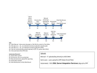
Novel Stand-Alone Small Hydro Renewable Energy System. Professor Dr. Adel M Sharaf ECE Dept-UNB, Canada. Outline. 1. Introduction and Background Review of Hydro Power Generation 2. Area of Research : What was the Task? What was the so called “Novel” Contribution or Strategy?

E N D
Novel Stand-Alone Small Hydro Renewable Energy System Professor Dr. Adel M Sharaf ECE Dept-UNB, Canada
Outline • 1. Introduction and Background Review of Hydro Power Generation • 2. Area of Research : • What was the Task? • What was the so called “Novel” Contribution or Strategy? • 3. Conclusions, Future Research Work & published papers.
The Hydro Power Advantage • Unique operational (Storage) flexibility • Can provide base load and peak load • Best source to support the development of other renewables such as wind, solar, etc • Low operational costs and long life span • Has over-whelming public support and over a Century old Engineering Experience • Renewable, low-emitting source of energy • Energy-efficient and cost-effective
Canada’s Role as a Hydro – Power Producer • Hydro-power represents approximately 10% of Canada’s electric supply,which accounts for over 90% of all renewable energy in her. Coal fired plants, at 52%, provide the largest source of electric generation. • Principal source of clean, low-emitting and renewable energy in the world (92%) • Canada is one of the world’s biggest hydropower producers (13% of global output) • Canada is the world’s second largest electricity exporter and over 60% of exported electricity is generated by hydropower • Total electricity export revenue for all of Canada for the 2002 calendar year: $1.8 billion
The Classification of the Hydro-Electric Systems • By Capacity - large, small, Micro • By Types of Installation - Impoundment, diversion, pumped storage • By Type of Turbines- Reaction and Impulse
The Capacity-wise Categorization • In this report the classification of HP by installed capacity is as follows : -Micro till 500kW - Mini :500kW < P ≤5MW - Small : 5MW< P ≤ 10MW - Medium: 10MW< P ≤ 50MW - Large: P > 50MW There is NO Strict Definition on Boundaries / Margin of Small Hydro Power System. Some say Small is up to 30 MW, while others are agreeing on 10 MW. In Canada, 10 MW is taken as the margin for Small Hydros.
By Types of Installation • Impoundment • large system • uses dam to store water • Diversion Type • River Diversion is used • Run-of-River • uses natural flow of river • does not require impoundment • Pumped Storage • when demand is low, water pumped back to reservoir • high demand, water is released
Type of Turbines The turbines can be divided into TWO main Categories, depending on their construction : • Reaction • Impulse The FOUR most common types of turbines used are: • Pelton Turbine.For Small Hydro Projects • Francis Turbine. • Propeller Turbine. • Kaplan Turbine. When choosing which one to use, its specific application and “head”, or the height of the standing water available to drive them, are taken into consideration.
Reaction Type Turbines • [ Depends on: head, flow, and pressure ] Reaction - used in large facilities • (Blades similar to boat propeller) Submerged in water • fully immersed in fluid • shape of blades produces rotation • Good for High Flow, Low head situations • One Example is Francis Turbine. • Another : Kaplan and/or Propeller Turbines [Kaplan is a type of Propeller Turbine
Kaplan Turbines • Kaplan turbine is a type of propeller turbine in which the pitch of the blades can be changed to improve performance. Kaplan turbines can be as large as 400 megawatts.”
Impulse Type Turbines • [ Depends on: head, flow, and pressure ] • Impulse Turbines are similar to water wheel (cupped Blades) • can be in open environment • water striking wheel causes it to turn • Example : Pelton Turbine • requires high head • High-head use- (Vertical drop > 10m) • High pressure (PSI)
Turbines can be split into four main groupings (although they do of course overlap and one may disagree on where one group starts and ends). These are :1. High head - above 100 m Turbine types are - Pelton, Turgo, High head Francis. 2. Medium Head - 20m to 100m Turbine types are - Francis, Cross Flow. 3. Low Head - 5m to 20mTurbine types are - Cross Flow, Propeller, Kaplan. 4. Ultra Low Head - below 5m Turbine types are - Propeller, Kaplan, Water wheel
Head (m) Head (m) Flow (m3/s) Power in kW » 7 x Head x Flow The Nominal Power Capacity of a Small Hydro Power System
Starting the Simple Power Calculations • Head • difference in elevation • Penstock • pipe that carries water from the reservoir • Turbine • converts linear kinetic energy to rotational kinetic energy • Generator • converts rotational kinetic energy to electricity
AN EXAMPLE OF A TYPICAL CALCULATION [Lower Kotmale Project, Sri Lanka] • DISCHARGE Q = 11370 Cubic Meters/SecondGROSS HEAD (H) = 33.2 mHYDRAULIC POWER = 11370X33.2X9.81 = 3703118.04 Watts = 3703.12 kWFRICTION LOSS =0.25X33.2 = 8.3 mNET HEAD (h) = 33.2 – 8.3 = 24.9 mNET HYDRAULIC POWER = 11370 X 24.9 X 9.81 = 2777338.53 Watts = 2777.34 kWEFFICIENCY OF TURBINE =80%NET MECHANICAL POWER =NET HYDRAULIC POWER X TURBINE EFFICIENCY = 2777338.53 x 0.8 = 2221870.8 W = 2221.9 kWGENERATOR EFFICIENCY = 91%ELECTRICAL POWER =NET MECHANICAL POWER X GENERATOR EFFICIENCY = 2221870.8 X 0.91 = 2021902.45 W = 2021.9 kW~ 2000 kW • The Total Power Generation for Four Such Francis Turbines : 4 * 2000 = 8000 kW, and considering the 0.8 System power factor The System Capacity is 10 MVA
Why Hydro – Power is renewable? Hydropower is considered a renewable resource because water, which nature makes available each year through the hydrologic cycle, is used as the energy source to generate power. Rural Electrification Policy • The important part of Rural Electrification is the mobilization of Renewable Energy (RE) sources, where they are cost-effective, and the promotion of RE technologies
How to Electrify Rural Areas or Best Sources for a Stand-Alone System Renewable Small hydro energy utilization is one of the most valuable answers to the question of how to offer electricity to isolated areas or rural communities electrification. It can answer to the many of the more complex problems of energy supply. The Types of Small Hydro Power System • The Small Hydro Power Systems can be divided into TWO Main categories : • 1. Robust Grid Connected • 2. Stand Alone
Again, the Small Stand-Alone Hydro Power Systems can be divided into TWO Main categories : 1. Constant Voltage – Constant Frequency (CV – CF) or 2. Variable Voltage – Variable Frequency (VV – VF)
The Traditional way of achieving (CV – CF) Constant Voltage, Constant Frequency in Stand-alone Asynchronous Generator run Hydro Power System • Using a controlled inductor in parallel with Capacitor providing self excitation • Using the Secondary Thermal Loads (connecting and releasing them according to the Torque, Load Excursions etc. through a Controller (Automated) • Manually Operated Situation in Rural Power Supply In Developing Countries like Sri Lanka, Kenya, Rwanda, Burundi, Madagascar, Myanmar
The Research Tasks • Suggest a NOVEL method to achieve a better Voltage / Speed Controls in a VV – VF System • Suggest the best location to have a such a Novel Device • Check the validity of Sharaf Error driven Tri Loop Dynamic Controller in a such Power System [VV-VF].
The Sample VV – VF Stand-Alone Small Hydro System System has Linear, Non Linear and machine Loads How you solve the Reactive Power problem, as you are dealing with an asynchronous generator? Where are those Traditional Dumb Loads? Why Matlab / Simulink? But, not Matlab, C or Fortran programming?
The Modulated Power Filter and Capacitor Compensator [MPF / CC] How you select R? The Carrier Frequency? Why IGBTs/Mosfets? Can’t I go for GTOs or Thyristors or IGBTs?
The New Proposed Way :Novel Modulated / Switched Power Filter and Compensator Capacitor
The Power System with attached Modulated Power Filter / Compensator Capacitor [MPF / CC] at Generator Bus
Tri loop Controller • It has Three Arms • Derivatives are added here as in the forms of Delays to introduce leads. Therefore for that reason we can argue the we have PID Controller instead of the visible PI Controller. • First Arm Controls Voltage [Stablizes] • Second Arm takes control of rapid changes occur in the System [ As the Current is more (quick) susceptible to transient situations than voltage. • Third Loop Optmizes the Maximum Power Use and reacts as Power Quality Enhancer. • How to find Kp and Ki? Is Trial and Error the answer?
Controller Parameter Selection • The basic design rules that are followed to determine optimized control parameters are based on the off-line guided trial and error -minimization method developed by Dr. A.M. Sharaf. Controller parameters are selected by a guided off line trial and error method based on minimizing selected error weighted performance index [27]. • Define an excursion based performance index; • Minimize : • (1) • (2) • (3) (4) • where, Tsample is the largest system mechanical time constant, ev(K) is the voltage error, ei(K) is the current error, Gv and Gi and are the weighting factor for voltage and current error. Only dynamic voltage error-tracking controller is considered here. If an additional loop is used, the additional weighting factor and error factor should be included in the equation (4) increase of additional loop of the current error-tracking controller.
Dynamic PI Tri-loop controller with Generator Voltage, RMS current, Speed Tracking Loops. (Developed by Dr. Sharaf)
Double loop dynamic tracking error controller (for combined dynamic voltage and current error stabilization). (Developed by Dr. Sharaf)
The Applied Methodology • Three systems we had to simulate on four different conditions, in order to reach a conclusion. (Next Slide). The Three Systems are : • Normal Power System without any added Filter • The Normal System together with MPF/CC at the Load Bus • The Normal System together with MPF/CC at the Generator Bus. Each System was simulated on four different conditions [Please See the Next Slide] to identify the following issues: • The System performance on those conditions : The Voltage drop, Stability of the System, Reactive Power Consumption • To identify the necessity of MPF/CC, and/or to see the achieving improvements when the filter is installed. • To identify the best possible location for MPF/CC installation.
Comparison of the Simulated Results • The Results can be logged in to a Table for comparison purposes. • As seen from the table there were 12 Simulations in total to be carried out to get the required data.
Testing the System for Short Circuits and Open Phase Conditions
Results • The MPF and Capacitor Compensator-MPF/CC Facts Device is very effective and Results are acceptable as Voltage / Frequency Control is within +/- 17% . • [We expecting better results, as fine tuning is to be done with the controller.]
CONCLUSIONS AND FUTURE WORK • The Project modeled and validated a novel FACTS based dynamic Switched Filter and Compensator developed by Dr. A. M. Sharaf and used in a small hydro renewable energy scheme employing a robust low cost induction generator. • The Novel Modulated Power Filter and Capacitor Compensator [MPF/CC] is switched using a multi loop error driven controller to stabilize the load bus voltage and more dynamic reactive power compensation under prime mover electric load switching and temporary short circuit faults. • The Project validated Dr. Sharaf’s Novel MPF?CC Facts Device-Design and the proposed control scheme in the area of voltage Stabilization Security and operational reliability of standalone small hydro renewable energy system in remote / village community electricity supply. • The Future works include the validation of other FACTS based compensators in small hydro, wind and hybrid diesel schemes, such as Statcom and other control strategies.
My Contribution • Developing MPF/CC to present [MPF/CC Idea is belonged to Dr. Adel M. Sharaf] • Developing a Sinusoidal Pulse Width Modulator written in MATLAB Programming Language as a Part of Making Program Modules instead of Simulink Models. • Validate the Sharaf Tri Loop Controller for VV – VF Systems. • Fine Tuning of the MPF/CC and Tri Loop Controller Parameters.
Published Papers • “A Novel Facts Stabilization scheme for a Stand-Alone Small Hydro Scheme” Submitted to IEEE CCECE – 06, Ottawa, Canada by Adel M. Sharaf and Senaka Jayawardhane
Thank you for your attention! Questions ?