Download
1 / 61
660 likes | 1.05k Views
MISCLLANEOUS MEASURING INSTRUMENTS. PRESENTATION BY: Er. Satnam Singh Lecturer(Electrical engg.) GPC Mohali (Khunimajra). Contents. Miscellaneous measuring instrument Measurement of resistance ( Meggar and earth tester) Frequency meter Power factor meter Phase sequence indicator

E N D
MISCLLANEOUS MEASURING INSTRUMENTS PRESENTATION BY: Er. Satnam Singh Lecturer(Electrical engg.) GPC Mohali (Khunimajra)
Contents • Miscellaneous measuring instrument • Measurement of resistance (Meggar and earth tester) • Frequency meter • Power factor meter • Phase sequence indicator • Instrument transformer(C.T. and P.T.)
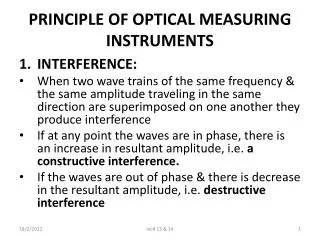
MEASUREMENT OF RESISTANCE • Resistance is defined as the property of a conductor or material by virtue of which it opposes the flow of electric current. • Resistance of a conductor, R=ρ l/a • From the point of measurement resistance can be classified as under • Low resistance • Medium resistance • High resistance.
MEASUREMENT OF RESISTANCE • Low resistance : resistance having their values of about 1 Ω or even less than that are known as low resistances. The armature winding, series field winding or large machines and shunts of ammeter come under this category • Medium resistance : resistance having their values between 1Ω to 100KΩ are included in this class. Most of the electrical apparatus used are of medium resistance. • High resistance.resistances of value 100KΩ and above are generally known as high resistances. Under this category comes insulation resistance, volume resistivity of material and surface resistivity.
MEASUREMENT OF LOW / MEDIUM RESISTANCE • The various methods used for the measurement of low resistances are • By ammeter voltmeter method • By wheatstone bridge method • By double kelvin bridge method
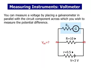
MEASUREMENT OF LOW RESISTANCE • AMMETER-VOLTMETER METHOD • In this method, current through the resistance under test and the potential difference across the resistance are measured with the help of ammeter and voltmeter. • The ratio of P.D. to the current gives the value of resistance R= V / I Ω
MEASUREMENT OF LOW RESISTANCE • WHEATSTONE BRIDGE • Wheatstone bridge consist of four resistance P, Q, R, and X connected in series and parallel. Resistance P and Q are fixed whereas resistance R is a variable resistance, X is unknown resistance whose value is to be determined . • There are two branches namely ABC and ADC. In both the branches point A is at the highest potential and point C at the lowest potential. • There is therefore a continuous fall of potential along each branch.
WHEATSTONE BRIDGE • By adjusting P and Q to suitable value and changing the variable resistance R such a condition can obtained that points B and D are at the same potential • Under such a condition a conductor joining B and D will carry no current. • In order to determine whether point B and D are at the same potential or not a galvanometer is connected between point B and D through a key K2 It is called bridge because galvanometer is a sort of bridge between B and D
WHEATSTONE BRIDGE • The Wheatstone bridge is said to be balanced if the galvanometer shows no deflection on closing the key k2 • It should be noted that the bridge can be balanced by properly fixing the value of P and Q and changing the variable resistance R. • The balanced condition of the bridge is sometimes called null point • The current in various branches are indicated according to the first law • Consider the closed loop ABDA according to KVL law we have • -I1P – IgG + (I - I1)R = 0…………….(1) • Similarly for closed circuit BCDB we have • -(I1 - Ig)Q + (I - I1 + Ig)X + IgG=0……………..(2)
WHEATSTONE BRIDGE • In balanced Wheatstone bridge the current through galvanometer Ig = 0 • hence from (1) we get • I1(P + R) = IR………………………………….(3) • And from (2) we get I1(Q + X) = IX………….(4) • Dividing (3) by (4) we have(P + R) / (Q + X) = R / X • PX + RX = RQ + RX • PX = RQ • P / Q = R / X • X = R. Q/P • Thus the value of unknown resistance can be determined by balancing the Wheatstone bridge
MEASUREMENT OF VERY LOW RESISTANCE • KELVIN DOUBLE BRIDGE METHOD • In Wheatstone bridge error like contact resistance, resistance of connecting leads etc occur it do not allow the use of Wheatstone bridge for the measurement of very low resistance. • The measurement of very low resistance can be had by using double Kelvin bridge
KELVIN DOUBLE BRIDGE METHOD • Fig shows the network for the measurement of low resistance • Here X is an unknown resistance and R is a standard resistance of the same order of resistance and should be of same rating or of the higher current rating. • The two resistance X and R are connected in series with short link resistance having resistance r (of very low resistance value)
KELVIN DOUBLE BRIDGE METHOD • P, Q, p and q are the four known resistances. • Out of these two one pair (P and p or Q and q) is variable. • The rated current is made to pass through the two resistances X and R respectively from the battery. • A variable resistance and ammeter connected in the circuit, limit the flow of current. • A galvanometer is also connected between the points PQ and pq or between the terminal FK.
KELVIN DOUBLE BRIDGE METHOD • The ratio P/Q is kept same as that p and q. • These ratios are varied continously till the galvanometer shows zero reading on the scale. • When galvanometer indicate zero position on scale it is called Null point and the meter is said to be balanced.
KELVIN DOUBLE BRIDGE METHOD • In balanced position of the bridge the direction of flow of currents in the bridge are shown. • Applying Kirchhoff's second law to the meshes AHFKBA and FEDCKF we get • I2P - I1p – IX = 0 • IX = I2P – I1p ……………1 • And I2Q – I1q – IR = 0 • Or IR = I2Q – I1q ……………2 • Dividing equation 1 by equation 2 we get • X/R = (I2P – I1p) / (I2Q – I1q) • X/R = P(I2 – I1p/P) / Q(I2 – I1q/Q) • As we know ratio of P/Q and p/q is same • Therefore X / R = P / Q • X= (P / Q) * R
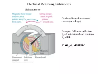
OHM-METER • This is the portable instrument which indicate the value of resistance to be measured by means of pointer and a scale these instrument indicate medium and high resistance. • The ohm meter is essentially a permanent magnet moving coil instrument but without the control spring. • Fig shows an ohm meter . It consist of two coils. The current coil C and pressure coil P fixed at right angle to each other. • There is a pivoted magnetic needle to which a pointer is attached moving over a scale extending from zero to infinity. • The supply is given to terminal a, a by means of a small permanent magnet hand driven generator generating about 500V
OHM-METER • The action of ohm meter is as given below : • The unknown resistance is connected between the terminals X-X. • Supposing the unknown resistance to be infinity(i.e. circuit is open). Then the generator voltage will be across the pressure coil only and no current will pass through the coil C . • The field generator by this coil exerts torque on the pointer so that it aligns itself along the axis of the coil P and the pointer points to infinity. • In the other case if terminals X-X are shorted, this will result that all the current flows through the low resistance current coil. • The field will exert torque on the pointer so that it aligns itself along the axis of the coil C and the pointer points to zero on the scale. • The scale is graduated in the ohms. The intermediate points may be obtained by calibration.
MEGGAR • Meggar is an instrument used for the measurement of high resistance and insulation resistance. • It consist of hand driven generator and a direct reading true ohm meter. • Fig shows the electrical connection of the meggar. The magnetic fields for both i.e. generator as well as meter is provided by the permanent magnets. • The moving system of meggar consist of three coil : current coil, pressure coil, compensating coil which are mounted rigidly on pivoted shaft which are free to rotate over a C shaped iron core.
MEGGAR • The coils are connected to the circuit by means of flexible wires, that exerts no restoring torque on the moving system. • Hence the moving system may take up any position over the scale when the generator handle is stationary. • The current coil is connected in series with the resistance R, between generator terminals and the test terminal marked L and E. when the terminal are short circuited and the generator handle is moved, a heavy current passes through the current coil. Then resistance R also control the range of the instrument.
MEGGAR • The P.C. is in series with a compensating coil and protection resistance R and is connected across the generator terminals. Compensating coil is provided to obtain better scale proportions. • When the current from the generator flows through P.C. the coil tends to set itself at right angles to the field of the permanent magnet. • When the test terminals L and E are open, corresponding to infinite resistance, no current flows through the deflecting / current coil. • The torque so produced rotates the moving system of the megger, until the scale point infinity, thus indicating that the resistance of the external circuit is very large for the instrument to measure.
MEGGAR • When the testing terminal L and E are short circuited through a low resistance then a heavy current passes through the deflecting coil or current coil to produce sufficient torque to overcome the anticlockwise torque of P.C. the moving system points to zero, thus showing that the external resistance is too small for the instrument to measure. • When a resistance under test is connected between the terminals L and E , the opposing torque of the coils balance each other, so that the pointer comes to rest at some intermediate point on the scale and thus the pointer indicates directly the value of resistance under test.
MEGGAR • OPERATION: The resistance under test is connected between the test terminals L and E. the generator handle is then steadily turned at uniform speed. • The turning of the handle is then steadily turned at uniform speed. The turning of the handle must be kept up, until the pointer gives steady reading. The reading on the scale gives resistance in mega ohms
EARTHTESTER • The earth tester is a special type of ohm meter which sends a.c. through earth and d.c. through measuring instrument • It has four terminal namely P1, C1, P2 and C2 brought outside. • Two terminal P1 and C1 are shorted to form a common point, which is further connected to their earth electrode as shown in fig. • The other two terminal P2 and C2 are connected to terminal P and C respectively. • The handle is made to rotate at a uniform speed. • The direct indication of earth tester gives the Earth Resistance
EARTHTESTER • Although the earth tester which is permanent magnet moving coil instrument and can operate on dc only yet by including the reverser and the rectifying device it is possible to make the measurement with ac flowing in the soil. • The use of ac passing through soil eliminate unwanted effect of due to production of back e.m.f. in the soil on account of electrolytic action.
MEASUREMENT OF FREQUENCY • The frequency of an A.C. circuit can be measured by various methods. As the frequency of supply from a local alternator can be determined by knowing the number of poles of the alternator as well as the speed of the given alternator. • The frequency f = N.P/120 • The other method of measuring frequency of the order of 50-100 c/s is with the help of portable instrument known as frequency meter
FREQUENCY METER • The frequency meter operate on the following principles • Mechanical resonance • Electrical resonance
FREQUENCY METER(Mechanical Resonance Type) • This type of instruments operate on the principle of mechanical resonance. • It consist of no. of thin steel strips placed in a row along side and close to electromagnet as shown in fig • These steel strip are known as reeds. The bottom portion of reed is fixed, whereas the upper portion of the reed is kept free to vibrate .
Contd. • A bent is given to upper portion of the reeds and are painted white at the top to distinguish them against black background. • The electromagnet of vibrating reed frequency meter is wound with a large no. of fine wires and is connected in series with a resistance across the supply whose frequency is to be measured • The dimension of all the reeds are not similar but differ slightly so that mechanical vibration of each reed is different. • The reeds are so designed and arranged in ascending order of natural frequency
Contd. • When the frequency meter is connected across the supply whose frequency is to be measured, an alternating flux is set up. Due to this alternating flux an attractive force is experienced upon the reeds every half cycle. • The result is that all the reed tend to vibrate but only the reed whose frequency is double of the supply frequency will vibrate with max amplitude. • If the two adjacent reeds vibrate with equal magnitude, then the supply frequency will be half way between the frequencies of the two adjacent reeds.
Contd. • Fig a shows when the supply frequency is 50Hz, then the vibrating reed having natural frequency 50Hz, vibrate with max amplitude. • Fig b shows when the frequency is 49.50 then the reed having frequencies of 49 and 50 vibrate with equal and maximum amplitude. • Fig c shows that no reed is vibrating which simply means that either exciting coil are not energised or frequency under measurement is out of range of the instrument.
FREQUENCY METER(electrical resonance type) • This type of instrument operate on the principle of electrical resonance, when inductive reactance XL and capacitive reactance Xc become equal, electrical resonance said to be occurred.
FREQUENCY METER(electrical resonance type) • This type of instrument consist of a laminated iron core of varying cross section, a fixed coil (known as magnetizing coil) mounted at one end of the iron core, moving coil attached with a pointer and pivoted so that it can move freely over an iron core. • The moving coil is further connected to a suitable capacitor “C” whereas the magnetising coil is connected across the supply terminal whose frequency is to be measured.
FREQUENCY METER(electrical resonance type) • The operation of the frequency meter can be understood from the phasor diagrams shown below: • When the magnetising coil is connected across the supply, then the current I flows through the magnetising coil and sets up flux ɸ. If we neglect the resistance of the coil and the iron losses in the core, flux ɸ is in phase with current I. • Since flux ɸ is an alternating flux, it will induce e.m.f. in the moving coil.
FREQUENCY METER(electrical resonance type) • This e.m.f. induced circulate a current in the moving coil. The current in moving coil will be lagging or leading depend upon the circuit of moving coil , wheather it is largely inductive or capacitive as shown in phasor diagrams. • When inductive and capacitive reactance are equal, current I will be in phase with e.m.f. i.e. as shown in fig c.
FREQUENCY METER(electrical resonance type) • The deflecting torque acting on the moving system will be proportional to I.i.cos(90_+ɵ) • Where I is the current in the field or magnetising coil, i is the current in the moving coil and ɸ is the angle b/w current and e.m.f. • Fig a shows a phasor diagram in which moving coil is assumed to be inductive therefore current, i lags behind the voltage by an angle ɸ. The torque acting on moving system Td α cos (90-+ɵ)
FREQUENCY METER(electrical resonance type) • Fig b shows the phasor diagram in which moving coil is assumed to be largely capacitive therefore current i lead the voltage by an angle α. Deflecting torque Tdœ i.cos (90-α)
FREQUENCY METER(electrical resonance type) • Fig c shows the phasor dia when the inductive reactance XL is assumed to be equal to capacitive reactance Xc. Under this condition the moving coil circuit is purely resistive, so the current i will be in phase with e.m.f. “e” • Therefore deflecting torque Td œ i. cos 90 =0
FREQUENCY METER(electrical resonance type) • The capacitive reactance of the moving coil i.e. Xc is constant for a given frequency f where as inductive reactance XL of the moving coil is not constant because its value varies with the position of moving coil on the iron core. • The inductance of the moving coil circuit decrease as the moving coil goes away from the magnetising coil. • Now coming to actual operation of the instrument, if the frequency is more, then inductive reactance XL will be more than capacitive reactance Xc, then torque will act on the moving system. • So under the influence of this torque, the moving coil will not move untill XL = Xc. • When XL and Xc are equal, no torque acts on the moving system, therefore it will not move further. • The position of the indicator will indicate the frequency at this instant.
FREQUENCY METER(electrical resonance type) • The value of capacitor C is so selected that the moving coil take up a convenient position on the iron core. • If supply frequency increases, the capacitive reactance decreases, therefore the moving coil then moves away from the magnetising coil till its inductive reactance becomes equal to capacitive reactance of the circuit. • If the supply frequency falls, the capacitive reactance becomes more than inductive reactance of the circuit, then the moving coil moves towards the magnetising coil till its inductive reactance becomes equal to capacitive reactance of its circuit.
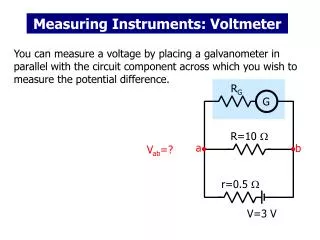
POWER FACTOR METER • The instrument used for the measurement of power factor is known as power factor is known as power factor meter • Power factor may be defined as • Cosine of the angle between voltage and current • The ratio of true power and apparent power V.I.cosɸ / V.I.
POWER FACTOR METER • Fig shows an arrangement for finding the power factor of the load. The true power is measured by a wattmeter and the apparent power is calculated by the product of voltage and current, therefore the power factor of a single phase circuit can be calculated by noting down the reading of wattmeter, voltmeter and ammeter respectively. • Power factor meter have two circuit namely current circuit and pressure circuit. The current circuit carries the load current or fraction of a load current whose power factor is to be determined and pressure circuit is split up into two parallel circuit, one circuit is non inductive and the other is inductive. • The deflection of the instrument depend upon the phase difference of the load current and the currents in the two branches of the pressure circuit i.e. upon the p.f. of the load
SINGLE PHASE DYNAMOMETER TYPE POWER FACTOR METER • It consist of two circuit • Current circuit • Pressure circuit • Current circuit consist of two fixed coil CC connected in series with the load and carries the load current . The pressure circuit also consist of two identical coil P1 and P2 of fine wire pivoted at the same spindle and both are fixed at 90* to each other . • The pressure circuit coil P1 is connected across the supply ends through a non inductive resistance R and pressure circuit coil P2 is connected across the supply terminals through an inductance L.
SINGLE PHASE DYNAMOMETER TYPE POWER FACTOR METER • The value of resistance and inductance are so selected, that for normal frequency, the current in both the pressure coil P1 and P2 are same. • Since the current in both the pressure coils is the same, therfore they will produce equally strong magnetic field which are 90* displaced from each other. • If the phase displacement is not exactly 90* it can be compensated by making mechanical angle between the two axis of coils P1 and P2 equal to electrical angle of difference between the two currents • The pressure coil P1 and P2 form the moving system and they move together. A pointer is also attached with the moving system which indicates the power factor of the circuit directly. The instrument has no controlling torque therefore the pointer remain in its deflected position
SINGLE PHASE DYNAMOMETER TYPE POWER FACTOR METER • WORKING: • When the instrument is connected in the load circuit, current flows through the current coil CC and pressure coil P1 and P2. • The magnetic field is set up by all these four coils, due to the interaction of the fluxes, the turning moment or torque is produced. • The moving coil start moving and turn to such a position that the resultant torque experienced by these coil is zero.
SINGLE PHASE DYNAMOMETER TYPE POWER FACTOR METER • Unity power factor: when the instrument is connected in the load circuit having unity power factor. The current in pressure coil P1 will be in phase with the load current or current in current coilCC and the current in pressure coil P2 will lag by 90* behind the voltage or behind the current in current coil CC. the coil P1, therfore will experience a turning moment and will adjust itself at a perpendicular to axis of CC and the pointer will indicate unity power factor
SINGLE PHASE DYNAMOMETER TYPE POWER FACTOR METER • Lagging power factor: when the instrument is connected in the load circuit having lagging power factor, in this case both the pressure coil P1 and P2 would experience turning moment in opposite direction and therefore, the moving system will adjust itself at a position in between 0 and 1 depending upon the value. • Leading power factor : when the instrument is connected in the load circuit having leading power factor, in this case, the polarity of field in current coil is reversed of that considered above. Hence the moving system takes up an intermediate position on the leading side in between 0 and 1
PHASE SEQUENCE INDICATOR • These instrument are used to determine the phase of three phase supply. • Phase sequence mean the order in which the phase of three phase supply attain their maximum value of e.m.f.’s. • If a 3 phase supply has a phase sequence as R,Y,B. • It means red phase will attain their maximum value of e.m.f. • Type of phase sequence indicator. • The two type of phase sequence indicator are • Rotating type • Static type
ROTATING PHASE SEQUENCE INDICATOR • The working principle of rotating type phase sequence indicator is same as that of 3 phase induction motor. • It consists of three coils connected in star, displaced at 120* apart from each other. • The three ends of the star connected coils are brought out and connected to the three terminals marked as R,Y,B as shown in fig • Three phase supply, whose phase sequence is to be determined is connected to the three coils of phase sequence indicator. • An aluminium disc is mounted on the spindle. The disc acts as a rotor and is free to rotate
ROTATING PHASE SEQUENCE INDICATOR • Working : • When three phase supply is given to the star connected coil, a rotating field is set up which induces eddy current in the disc. • A torque acts on the disc due to motor action. The disc start rotating • The direction of rotation depend upon the phase sequence of the supply. • An arrow is marked on the disc which indicate the direction of rotation of the disc. If the direction of rotation is the same as that of arrow head, the phase sequence is the same as marked on the terminals of the instrument. But if the disc rotates in the opposite direction the phase sequence is opposite to the marked on the terminal
STATIC PHASE SEQUENCE INDICATOR • These are of the following types • This arrangement consist of two lamp L1 and L2 and an inductor L in star connection as shown in fig when the sequence is R,Y,B the lamp L1 glow dim and lamp L2 glow bright. • If the inductor is replaced by equivalent capacitor C so that so that XL=Xc in this case, if the sequence is R,Y, B the lamp L1 glow bright and lamp L2 glow dim. • In some other case indicator L1 and L2 are replaced by neon lamp and inductor L is replaced by a capacitor C, resistance may be connected in series with the lamp to limit the current. • In this case lamp L1 will give full brightness and lamp L2 will not glow at all. It will remain dark, when the sequence is RYB