1 / 21

PIC18F4431

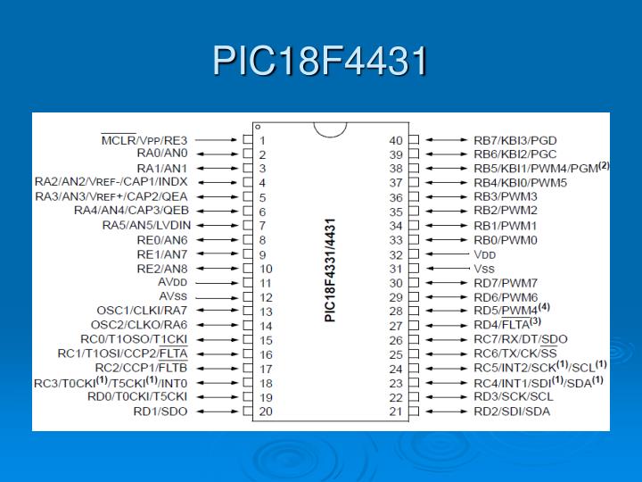
PIC18F4431. PIC18F1330. Infrared Encoder/Decoder. IrDA system block diagram. HSDL-3000. L298 Dual full-bridge driver. For higher currents, outputs can be paralleled. Pwm. 1. 0. t. a .T. (1 - a ).T. T. How to control DC motor speed ?. POWER. dir. H-bridge. from microcontroller.

sabina
Download Presentation

PIC18F4431

An Image/Link below is provided (as is) to download presentation Download Policy: Content on the Website is provided to you AS IS for your information and personal use and may not be sold / licensed / shared on other websites without getting consent from its author. Content is provided to you AS IS for your information and personal use only. Download presentation by click this link. While downloading, if for some reason you are not able to download a presentation, the publisher may have deleted the file from their server. During download, if you can't get a presentation, the file might be deleted by the publisher.

E N D

Presentation Transcript


  1. PIC18F4431

  2. PIC18F1330

  3. Infrared Encoder/Decoder

  4. IrDA system block diagram

  5. HSDL-3000

  6. L298 Dual full-bridge driver

  7. For higher currents, outputs can be paralleled

  8. Pwm 1 0 t a.T (1 - a).T T How to control DC motor speed ? POWER dir H-bridge from microcontroller DC motor Vmotor pwm • T is the period. • The duty cycle (a) is generally given in percent. • For a power supply of U volts, Vmotor = a.U.

  9. RC Servo Motor 3 wires: power, ground, control Control signal sets the position. High pulse every ~20 ms determines set angle; pulse width between ~0.5 ms and ~2 ms, indicating the two ends of angle range Internal gearing, potentiometer, and feedback control.

More Related