Download
1 / 32
350 likes | 525 Views
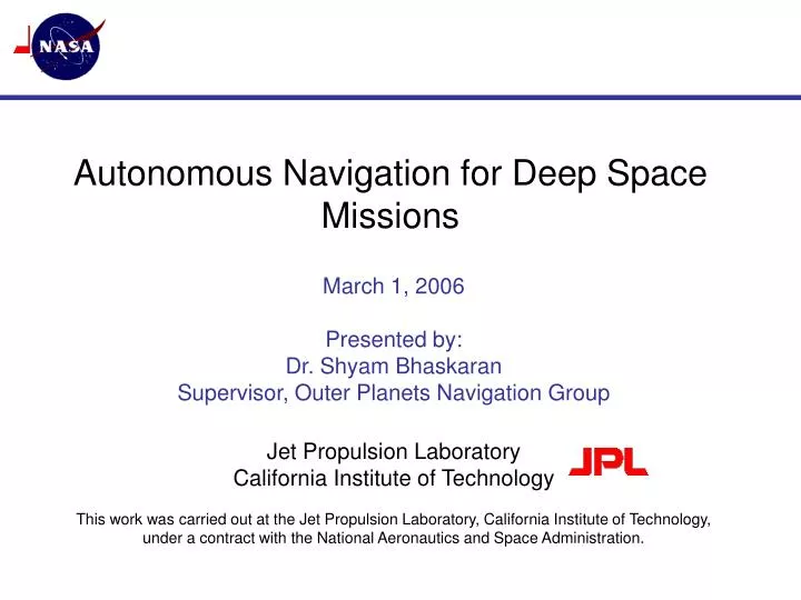
Autonomous Navigation for Deep Space Missions. March 1, 2006 Presented by: Dr. Shyam Bhaskaran Supervisor, Outer Planets Navigation Group Jet Propulsion Laboratory California Institute of Technology

E N D
Autonomous Navigation for Deep Space Missions March 1, 2006 Presented by: Dr. Shyam Bhaskaran Supervisor, Outer Planets Navigation Group Jet Propulsion Laboratory California Institute of Technology This work was carried out at the Jet Propulsion Laboratory, California Institute of Technology, under a contract with the National Aeronautics and Space Administration.
Agenda • Ground based navigation • Why Autonomy? • Overview of Autonomous Optical Navigation • Image Processing • Orbit Determination • Reduced State Encounter Navigation (RSEN) • AutoNav Interfaces with Spacecraft • Mission Results • Deep Space 1 • STARDUST • Deep Impact ACGSC Meeting, March 1-3, 2006
Ground-based Navigation • Ground-based navigation uses 3 main data types • Radiometric data types (two-way range and Doppler) to get spacecraft line-of-sight range and range-rate information from Deep Space Network tracking station • Delta Differential One-way Range (DDOR) to get plane-of-sky angular position of s/c relative to known quasar • Optical data from onboard camera to get target relative angular measurements, used on approach to target (primarily planetary satellites and small bodies) • Tracking data obtained using 3 Deep Space Network complexes • All data processed on ground to compute orbit solution • Ground-based maneuvers computed and uplinked to spacecraft • Limited by light-time, turnaround time to compute and validate solutions and maneuvers • Used successfully on missions to all planets (except Pluto), several small bodies, for many mission types (orbiters, landers, etc.) ACGSC Meeting, March 1-3, 2006
Why Autonomy? • Reduce mission cost • Tracking data involves use of Deep Space Network antennas • Limited resource • Cost directly related to amount of tracking time • Operations personnel • The more people needed for ground operations, the higher the cost • Increased science return • Round-trip light time to interplanetary spacecraft can be tens of minutes to several hours • Decisions about sequencing of observations therefore cannot rely on real-time data about spacecraft attitude and location • Build in conservatism so that observations cover all possible cases, resulting in data which has no science information • Use of onboard information can greatly improve ability to optimize science observations ACGSC Meeting, March 1-3, 2006
Why Not Autonomy? • Limited computer resources onboard spacecraft • Maturity of onboard navigation systems still low • Break-even point for cost vs. benefit not yet achieved • Limited decision making capability -- cannot react to parameters beyond the design • Inherent reluctance to relinquish control to onboard computer ACGSC Meeting, March 1-3, 2006
A Brief History of Autonomous Navigation used in Deep Space … • Deep Space 1 • 1st demonstration of fully autonomous onboard navigation • Cruise autonav used operationally until failure of onboard star tracker • Flyby autotracking used successfully at encounter of comet Borrelly • STARDUST • Encounter target tracking • Successful demo during flyby of asteroid Annefrank • Deep Impact • Autonav successfully used by Impactor spacecraft to hit lit area of comet as well as Flyby spacecraft to image impact site ACGSC Meeting, March 1-3, 2006
Autonomous Navigation Overview • Place certain computational elements of navigation onboard a spacecraft so it can compute its own orbit and maneuvers to achieve desired target conditions • Current version of autonav is based solely on optical data • Optical data is inherently easier to schedule and process • Unlike radio data, does not require the use of DSN antennas • Does not depend on Earth-based parameters which need to be updated • Media calibrations • Earth orientation parameters • Easier to detect anomalies • Addition of camera hardware to spacecraft, if not already needed, difficult to justify • Future versions will incorporate additional data types ACGSC Meeting, March 1-3, 2006
Autonomous Navigation Overview • Key elements of autonomous navigation system • Image Processing • Point source center-finding • Center of brightness • Multiple cross-correlation • Extended Body center-finding • Center of brightness • “Blobber” (largest contiguous object) identifier • Trajectory Numerical Integration • RK-7/8 N-body numerical integrator • Point-source gravity models • Solar pressure • Orbit Determination • Iterating batch-sequential least-squares filter • Optical-only observables • Estimates s/c position, velocity, bias acceleration, solar pressure, s/c attitude errors and rates • Maneuver computations ACGSC Meeting, March 1-3, 2006
Interplanetary Cruise - Optical Triangulation • Two lines-of-sight vectors to two beacon asteroids provides instantaneous position fix • Stars in camera FOV provide inertial pointing direction of camera boresight -- at least 2 stars needed for accurate determination of camera twist • In reality, two beacons will rarely ever be in the same FOV, and in any case, need better geometry than provided with two images in narrow angle camera • Individual LOS sightings incorporated into orbit determination filter ACGSC Meeting, March 1-3, 2006
Optical Triangulation • Accuracy of triangulation method dependent on several factors: • Ability to determine exact centers of stars and object in FOV (“centerfinding”) • Camera resolution • Distance from s/c to beacon object • Ephemeris knowledge of beacon object • With given camera and centerfinding ability, angular accuracy of LOS fix is proportional to distance of beacons from s/c and knowledge of beacons ephemeris • Asteroids make better beacon targets due to their proximity and number • As target becomes nearer, it becomes sole beacon ACGSC Meeting, March 1-3, 2006
Flyby and/or Impact Navigation • Target body becomes “extended” -- size greater than a pixel element • Series of angular measurements of target computed by finding center-of-brightness or other region on target body • Measurements combined in filter with a priori estimate of target relative position and velocity used to update target relative state to high accuracy • Due to large difference in brightness between stars and target, image processing done in starless mode • Inertial camera pointing taken directly from IMU data, which is not as good as using the stars • IMU bias and drift must be accounted for in filter to avoid aliasing attitude effects with translational motion ACGSC Meeting, March 1-3, 2006
Orbit Determination • Individual LOS fixes incorporated into filter to estimate complete s/c state • Position and velocity • Other parameters (solar radiation pressure, thruster mismodelling accelerations, gas leaks, etc) • OD filter • Linearization of dynamical equations of motion around reference trajectory • Partial derivatives of observables (pixel/line centers of beacon in FOV) with respect to state parameters used to form information matrix • Residual vector obtained from difference of observed beacon locations and predicts from reference trajectory • Solution at epoch obtained using batch least-squares formulation to solve normal equations • Dynamical equations of motion • Central body gravitation and 3rd body perturbations from planets • Solar radiation pressure and thruster accelerations • Integrated using Runge-Kutta 7-8 order integrator ACGSC Meeting, March 1-3, 2006
Maneuver Computation • Based on OD results, map filtered solution to desired target conditions • Determine miss distance from projected to desired target • At predetermined times, compute velocity adjustment needed to achieve desired target • Reconstruct achieved maneuver after execution using OD process • OR…continuous control of thrust pointing vector for ion propulsion system (e.g. DS1) ACGSC Meeting, March 1-3, 2006
Autonomous Target Tracking • During flyby, pace of events happening is much faster than during cruise • Quick turnaround OD solutions are needed to use late images of target to update pointing control • Ground-based navigation solution not possible due to round-trip light times • Reduced State Encounter Navigation (RSEN) • Uses simplified, linear model of s/c flyby past comet. • Uses optical images as sole data type, with images starting about E-30 minutes at a rate of about 1 image every 30 seconds. • Initialized using final ground or onboard estimate of spacecraft state relative to comet. • Observations accumulated for many minutes; 1st state update at about E-10 minutes. Subsequent state updates performed after every image acquisition. • Controls camera pointing only - no maneuvers performed to correct trajectory ACGSC Meeting, March 1-3, 2006
Autonav Interfaces with Spacecraft • Autonav system needs to talk to rest of spacecraft • Point camera to take images, either by turning entire spacecraft in case of fixed camera, or camera subsystem alone • Implement and execute maneuvers • Disseminate orbit information to Attitude Control System • Receive attitude, thruster information from ACS • Optimal to break out interface into real-time and non real-time sections • Real-time interface for high data rate information, such as ephemeris server, thrust history data • Slower interface used for basic image processing, OD, maneuver computation, and mini-sequence generation ACGSC Meeting, March 1-3, 2006
AutoNav Heritage Architecture Sequencing Subsystem (Main Sequence) Fault-Protect Subsystem ACS RCS Onboard-built MicroSequence S/C Side AutoNav Side Imaging Subsystem AutoNav Executive Gimbal Subsystem Nav Main Nav Real-Time DS1 Heritage Encounter Operations DI Heritage Picture Planning and Processing Orbit Determination Non-Grav History Maintenance Data-Update Management Ephemeris Server Maneuver, SEP Control ACGSC Meeting, March 1-3, 2006
Deep Space 1 • Background • DS1 was the first mission in NASA’s New Millennium Program - a series of missions whose primary purpose is technology validation. • 12 new technologies validated during DS1’s prime mission. These included: • Ion propulsion system • Autonomous optical navigation • Miniature Integrated Camera and Spectrometer (MICAS) • High power solar concentrator arrays (SCARLET) • Mission timeline • Launched on October 24, 1998 • Encounter with asteroid Braille on July 29, 1999 (completed primary technology validation mission). • Demonstrated cruise autonav • Failed to track Braille during flyby. • Due to grossly low signal from the APS camera channel (cause: inadequate camera calibration and extremely inopportune presentation geometry). • Led to lessons learned for future flybys ACGSC Meeting, March 1-3, 2006
Deep Space 1 • Extended science mission to rendezvous with short period comets Wilson-Harrington and Borrelly approved. • Sole onboard star tracker failed on November, 1999. • Spacecraft placed on extended safe-hold while new software developed and tested to use MICAS camera as replacement for star tracker. • Loss of thrust time resulted in inability to reach both targets, so Wilson-Harrington encounter was cancelled. • Cruise autonav system relied on star tracker, so remainder of cruise used standard ground-based navigation • New attitude control software using MICAS loaded and operational on June 2000. Thrusting resumes for Borrelly encounter. • Borrelly encounter on September 23, 2001. • RSEN successfully tracked Borrelly for 2 hours through closest approach ACGSC Meeting, March 1-3, 2006
Deep Space 1 • Encounter on September 22, 2001 • Flyby velocity of 16.6 km/s, distance at closest approach of 2100 km • RSEN initiated at E-32 minutes, based on ground-based navigation information from E-12 hours • A priori position uncertainties of 350 km in Radial (or equivalently, 21 seconds in time to encounter), 20 km in Transverse and Normal • A priori gyro bias uncertainty of 0.1 deg, drift of 0.3 deg/hour • Total of 52 images taken • 45 had Borrelly in camera FOV • Closest image taken at E-2 min, 46 seconds, at distance of 3514 km and resolution of 46 m/pixel ACGSC Meeting, March 1-3, 2006
DS1 Example - Comparison with Ground Radio OD During Interplanetary Cruise Flight OD vs. Ground Radio OD 7/21/99 ACGSC Meeting, March 1-3, 2006
Deep Space 1 ACGSC Meeting, March 1-3, 2006
Closest Image • Image shuttered at E-2min, 13 sec. • Distance of 3514 km. • Resolution of 40 m/pixel. ACGSC Meeting, March 1-3, 2006
STARDUST • NASAs fourth Discovery Mission, following Mars Pathfinder, NEAR, Lunar Prospector • Mission events: • Launch in February 7, 1998 • Asteroid Annefrank flyby on November 2, 2003 • Dress rehearsal for actual encounter • Successfully tested RSEN tracking of asteroid • Comet flyby on January 2, 2004 of the short period comet P/Wild-2. Flyby at comet relative velocity of 6.1 km/s • Successful tracking of comet during flyby • Earth return on January 15, 2006 with sample return capsule landing in Utah • Primary science goal was to collect 500 particles of cometary dust greater than 15 micron size and return them to Earth • Secondary science goal is to image the comet nucleus at a resolution of better than 40 m ACGSC Meeting, March 1-3, 2006
STARDUST • Encounter on January 2, 2004 • Flyby velocity of 6.12 km/s, closest approach at 237 km • RSEN initiated at E-30 minutes based on ground-based information at E-48 hours • Opnav information from E-14 hours available, but state errors considered to be of insufficient size to warrant additional command upload • A priori RTN position uncertainties of 1100x20x20 km (time-to-encounter equivalent of 9 minutes) • A priori gyro bias uncertainty of 0.1 deg • 114 total images taken • All 114 images containing the comet in the FOV (72 total images stored for downlink) • Closest image taken at E-4 seconds at distance of 239 km and resolution of 14 m/pixel ACGSC Meeting, March 1-3, 2006
STARDUST ACGSC Meeting, March 1-3, 2006
Deep Impact • NASA Discovery Mission • Mission timeline • Launch on January 10, 2005 • Comet impact on July 4, 2005 • Full autonav successfully used by Impactor to hit lit area on comet and Flyby spacecraft to image impact site • Engineering Objectives • Impact comet Tempel 1 in an illuminated area • Track the impact site for 800 sec using the Flyby s/c imaging instruments • Science Objectives • Expose the nucleus interior material and study the composition • Understand the properties of the comet Tempel 1 nucleus via observation of the ejecta plume expansion dynamics and crater formation characteristics ACGSC Meeting, March 1-3, 2006
Deep Impact ADCS aligns ITS Control frame with Relative velocity E-5 min AutoNav/ADCS Control E-2 hr Impactor Release E-24 hours ITM-1 E-90 min ITM-3 E-12.5 min ITM-2 E-35 min Tempel 1 Nucleus = 0.6 mrad 64 kbps 2-way S-band Crosslink Flyby S/C Science And Impactor Data Flyby S/C Deflection Maneuver Release + 12 min (101 m/s) 500 km Science and AutoNav Imaging to Impact + 800 sec Impact! Shield Attitude through Inner Coma ADCS aligns shield with relative velocity TCM-5 at E-30 hours Flyby Science Real-Time Data Shield Attitude Entry Look-back Imaging E+45 min Flyby S/C Science Data Playback to 70-meter DSS ACGSC Meeting, March 1-3, 2006
Deep Impact - Impactor • Impact on July 4, 2005 with impact velocity of 10.1 km/s • Full-up autonav system used • Autonav initiated at E-2 hr • Acquire imagesof the comet nucleus every 15 sec • Perform trajectory determination updates (OD) every minute starting 110 minutes before the expected time of impact • Perform 3 primary Impactor targeting maneuvers • ITM-1 @ E-90 min, ITM-2 @ E-35 min, and ITM-3 @ E-12.5 min • Acquire 3 images for Scene Analysis (SA) based offset @ E-16.5 min • Use SA offset for computation of final targeting maneuver • Align the ITS boresight with the AutoNav estimated comet-relative velocity vector starting @ E-5 min • Capture and transmit high-resolution images of the nucleus surface surrounding predicted impact site ACGSC Meeting, March 1-3, 2006
Deep Impact - Impactor ACGSC Meeting, March 1-3, 2006
Deep Impact - Flyby • Flyby velocity of 10.1 km/s at radius of 500 km • Autonav initiated at E-2 hours • Acquire MRI imagesof the comet nucleus every 15 sec • Perform trajectory determination updates every minute starting 110 minutes before the expected time of impact • Produce and hold deltaTOI and deltaTOFI time updates with every OD • Acquire 3 images for Scene Analysis (SA) based offset, relative to CB @ E-4 min • Used SA offset to correct HRI control frame pointing • Align edge of Solar Array with the AutoNav-estimated comet-relative velocity vector at shield mode entry • Shield mode defined to be when the estimated range is 700 km) ACGSC Meeting, March 1-3, 2006
Deep Impact - Flyby ACGSC Meeting, March 1-3, 2006
Future Enhancements • Small-body orbit case • Requires pre-determined shape model to correlate observed features with known features • Features can be limb/terminator or craters • Planetary approach and capture • Use satellites of planets as beacons (e.g, Phobos and Deimos for Mars) • Entry, descent, and landing • Use correlation of surface features, combined with ranging from Lidar • Rendezvous • Track satellite for on-orbit rendezvous or capture ACGSC Meeting, March 1-3, 2006