Download

1 / 14
140 likes | 312 Views
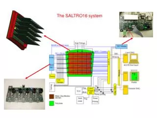
SALTRO16 activities in Lund. Lund University presented by Ulf Mjörnmark. EUDET/LCTPC setup in september 2010 . Low voltage. Front End Electronics. Kapton cables. TPC. Magnet. ALTRO based Front End Electronics & DAQ. Hardware is based on ALICE TPC readout electronics.

E N D
SALTRO16 activities in Lund Lund University presented by Ulf Mjörnmark
EUDET/LCTPC setup in september 2010 Low voltage Front End Electronics Kapton cables TPC Magnet
ALTRO based Front End Electronics & DAQ Hardware is based on ALICE TPC readout electronics
Summary of experiences with the ALTRO electronics -Excellent noise, ca 350 electrons on a FEC connected to the chamber -Operated reliably when taking data in test beams at DESY: 2009: February – March, July, September 2010: September, December -In September 2010 the system operated with: 7680 channels (60 Front End cards) 3 RCUs, 2 DRORCs Problems -Breakingamplifierchannels -Needs compressed air cooling . Not a practical solution for the future
Broken channels due to discharges in the GEM system? Happens too frequently , may in the worst case kill a FEC i.e 128ch. Has to be solved. Have emulated with injection of 1mJ in amplifier input. Kills the internal protection of the channel with same symptoms as real failure. External diode network as below works as protection for emulated input. Survives injection of 20mJ. Will be tested for noise . Testing on GEM chamber at next DESY test (june 2011). Evaluate. Final placement?
Front End Card Backplane New design LV LV CONTROL LV LV Pad plane SALTRO16 MCM Multi Chip Module 16 ch ALTRO PCA16 Kapton cable PAD plane
Protoypeplanningwithin AIDA time and resourceframe • It has been a workingassumption that the final LCTPC willhave the readout • electronics mounteddirectly on the outer face of the pad panel. • Such a solution has advantages and drawbacks and has to be carefullyanalysed • and compared to other options. • For the prototyping with SALTRO16, mounting on the pad panel it is not possible • since the channeldensity is toolow with 16 ch per chip, limiting the padsize • to 1*9mm (Only SALTRO16 on the pad plane, no othercircuitry). • Thuswe plan to place the SALTRO16 on a multi-chip-module (MCM) whichconnects to • the pad panel with the JAE connectorsused in the present prototype electronics. • The so called horisontal mounting as described on the followingslides is a viable • option also for the final LC-TPC as it offers manygood features compared to direct • mounting on the panel. • Wefind that an MCM module with 8 SALTRO16 chips is not a sound starting point • butrather a smaller MCM moduleshould be used.
Advantages of Multi Chip Module (MCM) compared to all electronics on the padpanel: • trace routing from pads to SALTRO16 becomes simpler - MCM module offers 2 extra layers for components. • electronics prototyping will be cheaper and easier. • parallell prototyping possible • possibility to distribute design and fabrication -analog and digital functions are well separated, - minimal heat transport to the TPCendplate • service by replacement of MCM module. • simpler endplate construction • SALTRO16 mounted on padpanel imply 1x9mm pads
Horisontal FEC-MCM design Back plane LV Voltage regulators FPGA Board CTRL LV&ctrl FEC-MCM Padpanel
Horisontal design Topside FEC-MCM 8 SALTRO16 128 channels Naked Si wirebonded to board Card size 31.5*23.5mm Pad pitch 1x5.9 mm possible Connectors to LV&CTRL board 4 connectors to pad board Belowside
6*6 matrix of FEC-MCM. Total 4608 channels, pad size, 1.0*5.9mm possible On a pad panel. 234 mm 170 mm Connector FEC-MCM 209 mm
But in the prototypestagewherewe are now and a couple of years to come we think that an FEC-MCM module with 128channels is too risky and expensive -Risky as long as the broken channel problem is not under control -Evenifweunderstand this problem, this electronics will be used in tests of variousavalanchechamberprototypes. This is a danger in itself. Expensive to replace 128 channelsifone is broken. Expensive to manufacturesince the chip yield is unknown and the chance of assembling 8 workingbutuntested chips on a board may be quitelow. The SALTRO16 is a ratherlarge chip. The yield can be as low as 85% (including bonding). Then only 40% of the modules will be OK if there are 8 SALTRO per module As a consequencewethink that mostprototyping has to be made with a smaller MCM module.
VERTICAL 32chMCM with 2 SALTRO Pad pitch 1x4.6 possible Bus card LV&CTRL 32chMCM SALTRO16 SALTRO16 PAD PLANE
SALTRO16: Evaluation at CERN: 201103-201105 MCM: Specification : 2011/03-2011/06 Design: 2011/09-2011/11 Fabrication: 2011/12-2012/01 Test: 2012/02-2012/04 Redesign and fabrication: 2012/05-2012/08 Test: 2012/09-2012/10 LV&CTRL/Buscard: Specification : 2011/03-2011/06 Design: 2011/07-2011/09 Fabrication: 2011/10-2011/11 Test with ALTRO+PCA16/SALTRO16: 2011/12-2012/01 Redesign and fabrication: 2012/02-2012/05 Test: 2012/06-2012/08 Small System test: MSM/LV&CTRL/Buscard:2012/11-2013/02 Final fabrication: 2013/03-2013/05 Full System test: 2013/06-2013/09 Input protection: Beam test at DESY: 2011/06 Evaluation: 2011/07-2011/08 PCMAG: to Japan: 2011/07 back: 2012/07