Download
1 / 54
540 likes | 623 Views
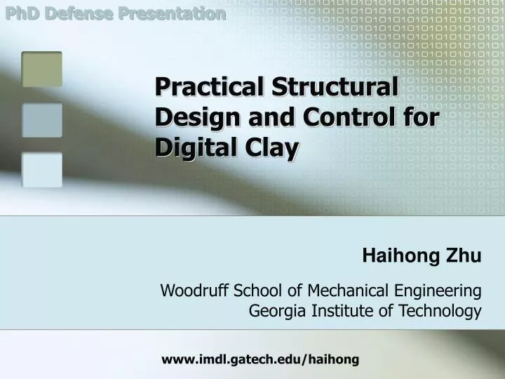
PhD Defense Presentation. Practical Structural Design and Control for Digital Clay. Haihong Zhu. Woodruff School of Mechanical Engineering Georgia Institute of Technology. www.imdl.gatech.edu/haihong. PhD Reading Committee Members. Dr. Wayne J. Book, Chair, Advisor, ME

E N D
PhD Defense Presentation Practical Structural Design and Control for Digital Clay Haihong Zhu Woodruff School of Mechanical Engineering Georgia Institute of Technology www.imdl.gatech.edu/haihong
PhD Reading Committee Members • Dr. Wayne J. Book, Chair, Advisor, ME • Dr. Imme Ebert-Uphoff, ME • Dr. Mark Allen, ECE • Dr. David Rosen, ME • Dr. Jarek Rossignac, COC
Outline of This Presentation • Introduction to Digital Clay • Cell of Digital Clay • Cell array of Digital Clay • Implementations of the multi-cell system • Conclusions and recommendations • Basic idea • Background & context • Hardware of Digital Clay • Control of Digital Clay • Advantages and potential applications • Overview & objectives • Cell level control • Control methods • Control states, switching logic and user gesture interpretation • Experimental system & results • Displacement measurement • PWM speed control and displacement estimation • Non-contacting resistance displacement sensor • Displacement sensor embedded micro actuator • 1x5 prototype • Summary • Overview & objectives • “N2 by 2N” fluidic matrix drive • Surface refresh methods for the fluidic matrix drive • Control architecture based on fluidic matrix drive • Summary • Overview & objectives • Mechanical structure design • Functional modules • Realization of “N2 by 2N” fluidic matrix drive • Displacement sensor embedded actuator array assembly • Pressure sensor array mounting base • Electronic system • Functional block diagram of the electronic system • Displacement sensor array multiplexing • 5x5 cell array prototype • Summary
Outline of Current Section • Basic idea • Background & context • Hardware of Digital Clay • Control of Digital Clay • Advantages and potential applications Introduction to Digital Clay
Introduction to Digital Clay Basic Idea • 3D human-machine haptic interface • Input / output using tangible 3D shape/surface • Computer controlled • Haptic/semi-haptic style • Can be edited / transferred digitally Video Haptic? Sense of touch
Introduction to Digital Clay Background & Context • Haptic manipulators • Tactile array • Haptic display interfaces
Introduction to Digital Clay Hardware of Digital Clay • General structure • Formable crust • Formable body • Planar pin-rod array • Composition • Actuator array • Sensors array • Fluidics system • Control system Actuator Array Video Fluidics System On-board Controller
Introduction to Digital Clay Sensor Sensor Sensor Actuator Actuator Actuator Cell System Cell System Cell System Control Structure • Cell Level Control • Surface Level Control • User API User AP I User API Surface Level Control API Interface Surface Level Controller Feedback Processor Command Bus Feedback Bus Cell Level Control Cell-Level Controller Cell-Level Controller Cell-Level Controller
Introduction to Digital Clay Advantages and Applications • Advantages • Natural, direct, fast and efficient communication • Unleash the mind power of creation, perception and intuition • Applications • Engineering design & science research • Medical diagnosis • Vision Impaired assistance • Military & civil map • Art • Communication • Education, Entertainment, etc. Video
Outline of Current Section • Overview & objectives • Cell level control • Control for solenoid valve based system • Control states, switching logic and user gesture interpretation • Experimental system & results • Displacement measurement • PWM speed control and displacement estimation • Non-contacting resistance displacement sensor • Displacement sensor embedded micro actuator • 1x5 prototype • Summary Cell of Digital Clay
Cell of Digital Clay Skin K x F b Overview and Objectives • Overview • Elementary unit of Digital Clay • Mimics a point on a material surface • One dimensional actuation type • Challenges • Control: • Haptic effect compromised by on-off valves • User gesture interpretation without other help • Volume change using unidirectional force (push) • No suitable displacement sensor • Micro actuator suitable for massive production • Objectives • Control algorithm to mimic a point on a material surface • Sensing methods • Actuator
Cell of Digital Clay Ff (External force) Pressure 12 Potentiometer Pressure Source Cylinder 10 Displacement Pressure (PSI) Solenoid Valves 8 Pressure Sensor 6 800 900 850 650 750 700 Time (milliseconds) Drain Tank Displacement Pressure Position Control Pressure Sensor Displacement Pressure Pressure Control Cell Level Control (I) • Control for solenoid valve based hydraulic system • Testing system setup • Pressure surge caused by solenoid valve • Pressure signal filtering • Position control vs. pressure control
Cell of Digital Clay External Force Ff b c Fy Edit mode External Force Ff Display mode a d Ff > Fy X0 X1 Actuator’s Displacement Elastic state Plastic state Ff < Fy a Fp b e Quickly remove finger or turn off the toggle switch Holding finger for 2 second while the toggle switch is on c Fl d Shaping state • Ff -- External Force Acting on the Actuator • Fy -- The Virtual Yielding Force Limit Feedback Control state selection Actuator’s Displacement Control law generation Control Law Timer/ Trigger PI control Plant Cell Level Control (II) • Control states, switching logic and user gesture interpretation
Cell of Digital Clay Input Force (Pressure PSI) 12 Ff (External force) 11 10 9 j f k b c Fy g i Potentiometer 7 e Pressure Source Fl d Cylinder h 5 4 Solenoid Valves 3 2 a l Pressure Sensor 1 0 5 10 15 20 25 30 -5 Actuation Displacement (mm) Drain Tank Cell Level Control (III) • Elastic state • Experimental system & results • Plastic state • Keep stationary • Shaping state • Exit shaping state
Cell of Digital Clay Where are we? • Overview & objectives • Cell level control • Displacement measurement • PWM speed control and displacement estimation • Non-contacting resistance displacement sensor • Displacement sensor embedded micro actuator • 1x5 prototype • Summary • Why is this topic important? • Sensor and actuator are critical • Huge number of sensors and actuators are needed • No suitable existing products are found
Cell of Digital Clay 13 PSI 11 PSI High Pressure Source 1 PSI Solenoid Valves Drain Tank Pressure Sensors Linear Actuator Cylinder Low Pressure Source Measuring System Potentiometer Displacement Measurement (I) • PWM Speed Control and Displacement Estimation • Experimental system & preliminary test results • PWM Frequency <100 Hz:High Linearity; Bad haptic sense • PWM Frequency >150 Hz:Low linearity; Good haptic sense
Cell of Digital Clay Displacement Measurement (II) • PWM Speed Control and Displacement Estimation • Analytic model used for curve fitting • Phase I Flow = 0 • Phase II • Phase III • Phase IV ! Definitions of terms can be found in the thesis
Cell of Digital Clay High Pressure Source Solenoid Valves Drain Tank Pressure Sensors External Force Speed and Position Control Using PWM 70 14 Cylinder Pressure across the Valve (Caused by Input Force) 60 12 50 10 Potentiometer Low Pressure Source 40 8 Pressure across the Valve (PSI) Cylinder Rod Displacement (mm) 30 6 20 4 Measured Displacement Ideal Displacement (Dashed Line) 10 2 0 0 0 0 500 500 1000 1000 1500 1500 2000 2000 2500 2500 3000 3000 3500 3500 4000 4000 4500 4500 5000 5000 Time (millisecond) Pressure Sampling Duty Required Speed Duty Generation One Step Delay PWM Generation Driver Position Estimation Required Position Stop Signal Position Sampling Recording Plotting Displacement Measurement (III) • PWM speed control and position estimation test • Test setup • Control structure • Test result Video
Cell of Digital Clay Goodness of fit: SSE: 1.297 R-square: 0.9999 Cylinder Bore Resistance Film Cylinder Rod Signal Out Piston (graphite) Proposed Sensor LVDT Uout C1 Uin Sensor DATA (mm) y vs. x 70 Fitted curve 65 60 55 REFERENCE DATA (LVDT) (mm) 50 45 40 35 30 25 20 25 30 35 40 45 50 55 60 65 70 75 Displacement Measurement (IV) • Displacement Sensor Embedded Micro Actuator • Non-contacting Resistance Sensor • Resistance to displacement signal • Capacitor picks up the signal • Structure • Micro glass tube + graphite piston • Uniform thin film deposited • Advantages • Ultra-compact size • Low cost • Interchangeable with LVDT • Nonlinearity < 0.5% • Resolution Theoretically Infinity
Cell of Digital Clay Where are we? • Overview & objectives • Cell level control • Displacement measurement • 1x5 prototype • Summary
Cell of Digital Clay Return Pressure Pressure Signal Low Pressure Valves High Pressure 1 x 5 Cell Array Prototype of Digital Clay • A line on a material surface • Structure Features • Micro Solenoid Valve • No Displacement Sensor • SLA10120 Base • Control • Direct control on each cell using proposed PWM method Video
Cell of Digital Clay Summary • Position control method is suitable for solenoid valve based hydraulic system • Proposed control states, switching logic and user gesture interpretation are effective for hydraulic system to mimic material mechanics properties with haptic senses • Novel displacement measurement methods suitable for large number and micro size hydraulic system are presented • PWM speed control and displacement estimation • Non-contacting resistance displacement sensor • Displacement sensor embedded micro actuator (patent in application) • 1x5 prototype gives one solution to realize the Digital Clay • Good experimental system & results are shown
Outline of Current Section • Overview & objectives • “N2 by 2N” fluidic matrix drive • Surface refresh methods for fluidic matrix drive • Control architecture based on fluidic matrix drive • Summary Cell Array of Digital Clay
Cell Array of Digital Clay Overview and objectives • Overview • Forms the human-machine interactive tangible surface • Planar pin-rod array (bed of nails) • Huge number of identical components involved • Challenges and solutions • Objectives • Conceptual design of practical structure suitable to realize cell array that has huge number of cells • Control architecture suitable for large scale subsystem array • Practical structure at current stage of technology • One dimensional actuation • 2.5 D • Hardware • Raw material cost • Manufacturing • Structural simplicity • Fluidic Matrix Drive • Control • Control resource • Dynamic control resource allocation
Cell Array of Digital Clay Hydraulic Actuator Row Control Valve Array Actuator Control Adaptor Row Control Valve Array Column Control Valve Array Low Pressure High Pressure High Pressure Low Pressure Column Valve Array Pressure Source Selection Valve High Pressure Low Pressure Pressure Source Selection Valve High Pressure Low Pressure “N2 by 2N” Fluidic Matrix Drive (FMD) (I) • 2N (+ 1 or 2) control valves control an N by N actuator array (needs 2N2 valves usually ) • Column and row matching style • Independently addresses every actuator • Greatly reduced the amount of valves and control resourse example. N=100, 2*1002 =20,000 >> 201 • Relatively slow
Cell Array of Digital Clay “N2 by 2N” Fluidic Matrix Drive (FMD) (II) • Working principle of the control adapter Control Adapter Column Control Valve Pressure Selection Valve Row Control Valve High Low Control Pressure
Cell Array of Digital Clay Control Adapter Column Control Valve Row Control Valve Surface Refresh Methods for FMD (I) • Model of the FMD Node Flow rate: Actuator displacement: • δ1 and δ2 are the PWM duty cycles applied to the valves • k is a constant • PWM waves are of the same phase
Cell Array of Digital Clay Surface Refresh Methods for FMD (II) • Reducing the FMD node model • Keep row control valve only on or off (PWM duty cycle = 0% or 100%)
Cell Array of Digital Clay 1st RRC 2nd RRC 1st RRC 2nd RRC Surface Refresh Methods for FMD (III) • Matrix representation of surface refresh • Working surface matrix representation • Surface refresh • α and β are the PWM duty cycle vectors applied on the column and row control valve arrays
Cell Array of Digital Clay Surface Refresh Methods for FMD (IV) • One-time refresh method • Process • Fully open one row valve; • Control the column valve array until the actuators in that row reach the desired final position; • Close that row valve; • Open the next row valve and repeat step 2. • Advantage and disadvantages • Simple • Slow • Bad visual effect and haptic effect In this example, actual total time taken is around 3.5 seconds
Cell Array of Digital Clay Surface Refresh Methods for FMD (V) • Gradual refresh method • Process • Divide the desired final surface into several intermediate surfaces; • Use one-time refresh method to achieve each intermediate surfaces. • Advantage and disadvantages • Good visual effect and haptic effect • Relatively complicated • Slower In this example, actual total time taken is around 5.5 seconds
Cell Array of Digital Clay Surface Refresh Methods for FMD (VI) • Gradual approximation refresh method • Process • Divide the desired final surface into several intermediate surfaces; • Decompose and translate intermediate surfaces into certain sub-surfaces; • Realize each sub-surface once a time; • When realizing each sub surface all the valves are activated at certain PWM duty cycle. • Advantage and disadvantages • Good visual effect and haptic effect • Most complicated • Very fast • Need further research In this example, total time taken is around 1 second
Cell Array of Digital Clay Cell Level Control Surface Refresh Coordinator Hot Area Processor Memory PWM Vector PWM Vector Cell Level Control Valve Controller Valve Controller ID1+ PWM Duty1; ID2+ PWM Duty2; … Control Valves Actuator & Sensor Valve Controller Multiplexers & Feedback Processor Valve Controller ID Recognition PWM Wave Generation Valve Driver Valve Driver Valve Controller Valve Array Control Architecture Based on FMD (I) • Cell level control • Surface refresh coordinator • Dynamic control resource allocation • Hot area processor
Cell Array of Digital Clay Desired material property for each cell to simulate Control Architecture Based on FMD Desired actuator array’s displacement matrix and the speed to achieve the displacement The matrix contains the information of user actions and intentions for each cell in the hot area GUI Desired [MP] User API CAD Model Other User Inputs [User Motion] Desired [X] &[V] Current [ X ], [ P ] To compensate the surface discrepancy caused by the delayed refresh on the surface other than the hot area • Surface Level Control • Position matrix decomposition • Contact detection • Control source allocation • Aftermath compensation Signal to tell surface refresh coordinator lower down its priority, and tell Hot area processor to work Desired actuator array’s displacement matrix in the next surface refresh cycle Current [ X ] & [ P ] Hot areas’ locations, sizes, etc. Desired [ X ] Compensation matrix [User Motion] Contact Process information Contact Process Signal Multiplexers & Feedback Processor • Surface Refresh Coordinator • PWM vector generation • Compensate structural variation Current [ X ] Current actuator array’s displacement matrix and pressure matrix PWM Vector Valve Controllers • Hot Area Processor • Haptic reaction • PWM vector generation • Aftermath compensation Current [ X ] & [ P ] PWM Vector Valve Controllers
Cell Array of Digital Clay Summary • “N2 by 2N” fluidic matrix drive is novel and has great benefits for large scale fluidic subsystem array. (Patent application) • Greatly reduces the control valves and control channels needed • Makes the cell array (with huge number of units) practical • Relatively slow speed maybe compensated using proper surface refresh method • Suitable surface refresh methods for fluidic matrix drive make it possible for the system using FMD to achieve smooth and fast surface refresh. • Carefully designed control architecture for FMD can both reduced hardware cost and computing resource.
Outline of Current Section • Overview & objectives • Mechanical structure design • Functional modules • Realization of “N2 by 2N” fluidic matrix drive • Displacement sensor embedded actuator array assembly • Pressure sensor array mounting base • Electronic system • Functional block diagram of the electronic system • Displacement sensor array multiplexing • 5x5 cell array prototype • Summary Implementations of the Multi-cell System
Implementations of the Multi-cell System Overview & objectives • Practical structural implementation • Aims at N by N cell array • Challenges • Objectives • Design for manufacturing • Modular design • Structural simplicity • Design for mass production • Design for scalability • Structural expandable • Size and resolution scalable • Vertically modular • Large number of identical components • Material cost, fabrication cost, assemble cost • Manufacture and assemble difficulty • Large number of feedback measurements • Hardware cost • DAQ resource limitation
Implementations of the Multi-cell System Mechanical Structure Design (I) • Functional Modules • Row control hydraulic board • Column control hydraulic board • Pressure sensor array assembly • Fluidic channel concentrating block • Actuator-sensor array assembly Actuator-sensor Array Assembly Row Control Valves Column Control Valves Fluidic Channel Concentrating Block Pressure Sensor Array Assembly Column Control Hydraulic Board Row Control Hydraulic Board
Implementations of the Multi-cell System Input channel Output channel Input channel Output channel Working chamber Column control valve Membrane Residue volume Control chamber Row control valve Mechanical Structure Design (II) • Realization of “N2 by 2N” fluidic matrix drive • Design of the control adapter
Implementations of the Multi-cell System Retracting Pressure Displacement Sensor To Control Valves Digital Switch Multiplexer Sealing Board Return Pressure Top Pressure Chamber Conductive Epoxy Sensor Embedded Cylinder Conductive Epoxy Bottom Plate Tube Racks Glass Tubes Plugs prevent graphite paste from getting into the tubes Graphite Paste Mechanical Structure Design (III) • Displacement sensor embedded actuator array assembly
Implementations of the Multi-cell System Pressure Sensor Leads Top Metal Plate Printed Circuit Board Bottom Metal Plate Branch Channel Main Channel Pressure Sensor Leads SLA Base Printed Circuit Board Branch Channel Main Channel Mechanical Structure Design (IV) • Pressure sensor array mounting base
Implementations of the Multi-cell System To Cell Level Control Filter Array Interfaces Pressure Sensor Array Multiplexer Multiplexer Driving Circuit Signal Conditioners Multiplexer Position Sensor Array Multiplexer Driving Circuit Valve Driver Array Control Valve Array Electronic System (I) • Functional block diagram of the electronic system
Implementations of the Multi-cell System Cs To A/D Converter U Excitation Voltage Signal Conditioner Vi V’ Ii R Cgi Ci Vk Ik Resistive Film Electronic System (II) • Displacement sensor array multiplexing • Simple multiplexing scheme
Implementations of the Multi-cell System 4 1000 Sensors 3.5 ||U|| (V) 3 2.5 100 Sensors 2 10 Sensors 1.5 1 Without Crosstalk 0.5 0 0 1 2 3 4 5 6 7 8 9 ||Vk|| (V) C1 = 18pf, C2 = 30pf, Cs = 0.3 pf, R = 1M Active sensor output: 0 - 10 volt Inactive channels’ outputs: 10 volt Electronic System (III) • Displacement sensor array multiplexing • Simple multiplexing scheme results
Implementations of the Multi-cell System Excitation Voltage Rg To A/D Converter Cs U Signal Conditioner Vi V’ Ii R Cgi Ci Vk Ik Resistive Film Electronic System (IV) • Displacement sensor array multiplexing • Multiplexing scheme using grounding resistor
Implementations of the Multi-cell System 40 35 Working Range ||U|| (millivolt) 30 25 20 1000 Sensors 100 Sensors 15 10 Sensors Without Crosstalk Rg = 20K Active sensor output: 0 - 10 volt Inactive channels’ outputs: 10 volt 10 10 ||Vk|| (Volt) 5 0 0 1 2 3 4 5 6 7 8 9 Electronic System (V) • Displacement sensor array multiplexing • Results of multiplexing scheme using grounding resistor
Implementations of the Multi-cell System To A/D Converter Signal Conditioner Electronic System (VI) • Displacement sensor array multiplexing • Other multiplexing schemes • Numerically compensate • Two Digital Switches
Implementations of the Multi-cell System Column Control Row Control To ADC Signal Conditioner Signal Conditioner Signal Conditioner 5x5 Cell Array Prototype • Designed and controlled using proposed solutions • Key Features • Stereolithography Technology • 5 x 5 actuators in a linear pattern • Grid size (center to center) is 5mm • Hydraulic Matrix Drive • Non contacting resistive sensors and modified pressure sensors • Reduced control signals for multiplexers • Controlled by RT Linux on a host PC
Implementations of the Multi-cell System Summary • Vertically modular design reduces the complexity of fabrication and assembly, improves the reliability and convenience for maintain, and suitable for mass production. • Successfully Designed FMD control adapter realized the concept of FMD • Displacement sensor embedded actuator array assembly makes fabrication of large number actuator-sensor array become simple and fast. • Pressure sensor array mounting technology reduces the cost and makes the multi-cell system expandable. • Carefully design electronic system can reduce the complexity of the control hardware, amount of components and improve the feasibility of realizing the Digital Clay. • Displacement sensor array multiplexing using grounding resistor is a simple but effective way to realize the large scale multiplexing. • 5x5 cell array prototype is designed under the guidelines suitable for N by N cell array, and can be expanded to larger size array. Test results preliminarily validated the design and control methods presented.
Conclusions (I) • System development • Cell level control architecture and realization • Haptic control for solenoid valve based hydraulic system (Position control, shaping state, user gesture interpretation) • Surface refresh methods for FMD • Surface level control architecture based on the FMD • Vertical modular design for multi-cell system • Key components design • Displacement sensor embedded micro actuator • Fluidic matrix drive for multi-cell system with huge number of cells • Pressure sensor array assembly