Download
1 / 19
190 likes | 346 Views
Integration of programmable logic into a network front-end of a telecontrol system. Supervisor: Professor Patric Östergård Instructor: Jouni Meriläinen, M.Sc. (Tech.) Organization: Netcontrol Oy. Contents. Objective of the thesis The field of electricity distribution

E N D
Integration of programmable logic into a network front-end of a telecontrol system Supervisor: Professor Patric Östergård Instructor: Jouni Meriläinen, M.Sc. (Tech.) Organization: Netcontrol Oy Henri Kujala
Contents • Objective of the thesis • The field of electricity distribution • Related subjects: network front-end, programmable logic • Implementation • I/O devices and data types • Configuration constructed for verifying results • Fault clearing application for testing purposes • Summary
Objective of the thesis • The purpose of integration of programmable logic into a network front-end of a telecontrol system is to offer a programmable logic platform • Aid in the automatization of the environment of remotely controlled stations, namely substations • Automatization for economical reasons and also to improve the usability of the network by increasing the level of reliability • The aim is to make the programmable logic environment co-operate with the front-end device
Field of electricity distribution • The field is geographically distributed • Unmanned remote stations • Telecontrol is defined as the remote transmission of operating information • Telecontrol applied in electricity distribution networks • Control and command of relays, breakers and switches • A master/slave model, where the control centre is the master and the slave stations are called substations • The key parameters of an electricity distribution network are voltages and currents
Front-end of a telecontrol system - NFE • A device resembling computers • CPU, memory, ports for communications, database for storage • Located at node points in the network • Front-end devices pre-process information exchanged between substations and the control centre • Used as protocol converters and data concentrators • An example of a front-end device is the NFE (Network Front-End) from Netcontrol • NFE504 is the specific NFE unit used throughout this thesis
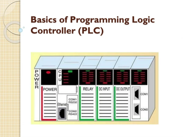
Programmable logic – PLC and softPLC • Programmable logic is used in the control of traffic lights, for example • Programmable logic controller – PLC • PLCs execute tasks in a loop, called the scan cycle • softPLC – software-based control • softPLC means that the functions of a PLC are executed on a PC platform in software • The selected softPLC application is ISaGRAF from ICS Triplex and it is used throughout this thesis as the softPLC environment • Other platforms also available
ISaGRAF environment • Hardware independent – portable • Consists of a workbench and a target • Workbench for programming the applications and target for executing these • Target: one virtual machine for one resource • Different target models: multi- and monotasking; medium (16-bit) and large (32-bit) • Project database is a Microsoft Access database
ISaGRAF input and output devices • There are two types of I/O-devices • Simple devices • Complex devices • Simple devices are one-way (input or output) • Complex devices are combinations of simple devices • An I/O-driver consists of a multiple of ISaGRAF devices
Implementation • ISaGRAF communicates with the NFE using NFElink protocol • Also an interface module called NFElinkITF is used in the communications process • NFElinkITF is an interface, which facilitates communications between ISaGRAF and NFElink • I/O interface for the connection between ISaGRAF and NFE was constructed
Implementation (2) • The structure of NFE data types is taken into account when constructing ISaGRAF I/O-devices • A dedicated ISaGRAF I/O device and data type for each NFE data type was created • The correspondence of the data types is almost one-to-one • The I/O interface constructed uses the created ISaGRAF data types to access the corresponding data types at the NFE
Cross-reference • Due to differences in addressing notation, cross-referencing is needed • ISaGRAF notation is of type %(I/Q)AX.Y.Z • I/Q stands for input/output, respectively • A is the type of channel • U for user generated and D for integer, for example • X.Y.Z is the channel number consisting of ISaGRAF device index (X), the index of the simple device inside the complex device (Y) and the channel number (Z) • NFE database addressing is as follows: • Group structure of 16 bits identifies the NFE channel and data type • A hexadecimal 32-bit index identifies the I/O point inside the group
Cross-reference (2) • One ISaGRAF channel is mapped into a combination of one NFE channel, one data type and one index in the group of data types • Example: • NFE channel 2, data type NPCCMD and index 0x02000003 (hex notation) is mapped into ISaGRAF data type ISACMD, channel 2, which here, in correct notation format is %QU0.2.2
Advantages of the implemented model • Advantages: • Easy to expand and improve • Benefits from NFElink • Redundancy of NFE’s handled by NFElink • Disadvantages: • One additional layer between the NFElink and ISaGRAF caused by the NFElinkITF
Configuration • A real-life environment • Process simulator based on Mitsubishi’s PLCs • Netcontrol’s Netcon 500 substation • NFE504 as the front-end device • IO64 cards for input/output • ISaGRAF softPLC environment • iFix industrial automation software for controlling and visualizing the demo configuration • NFElink + NFElinkITF for accessing the NFE database • PC computer for programming and executing the ISaGRAF logic
Application example • The application is an automatic fault clearing application • The fault clearing process is automatic, but the starting of the application has to be triggered (currently manually) • When clearing is finished, the trigger is reset • The automation of the starting of the fault clearing process is possible to accomplish with little effort
Fault clearing • The exchange of triggering information benefits from CMT (Connection Manager Test) module • The triggering information itself is virtual • Fault clearing in this process is sequential: • Open the switch • Open and close disconnectors for line testing • Close the switch to test if the fault still exists • Continue until the fault is separated from the energized line
Summary and suggestions for the future • Summary: • Programmable logic is executed with ISaGRAF • ISaGRAF is located on a PC platform and connects to the NFE for data transfer • The created data types correspond to the NFE data types • The application example proves that the co-operation of ISaGRAF and NFE is functioning properly • Suggestions for the future: • Implement the redundancy of the logic in order to improve reliability • Port the logic into the same functioning environment with the NFE or at least execute the logic on a real-time operating system