Download
1 / 38
400 likes | 785 Views
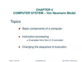
Chapter 4 The Von Neumann Model. Concepts to Learn…. Computer Architecture Von Neumann vs. Harvard MSP430 Architecture RISC / CISC Anatomy of an Instruction MSP430 Instructions Instruction Cycles Clocks MSP430 Finite State Machine. Forecasting Computer Technology.

E N D
Concepts to Learn… • Computer Architecture • Von Neumann vs. Harvard • MSP430 Architecture • RISC / CISC • Anatomy of an Instruction • MSP430 Instructions • Instruction Cycles • Clocks • MSP430 Finite State Machine Chapter 4 - The Von Neumann Model
Forecasting Computer Technology “I think there is a world market for maybe five computers.” Thomas Watson, IBM Chairman, 1943 “Computers in the future may weigh no more than 1.5 tons.” Popular Mechanics, 1949 “There is no reason anyone would want a computer in their home.” Ken Olsen, DEC founder, 1977 “DOS addresses only 1 MB of RAM because we cannot imagine any applications needing more.” Microsoft, 1980 “The 32-bit machine would be an overkill for a personal computer.” Sol Libes, ByteLines, 1981 “640K ought to be enough for anybody.” Bill Gates, 1981 Chapter 4 - The Von Neumann Model
OUTPUT * monitor * printer * LEDs * D/A * disk INPUT * keyboard * mouse * scanner * A/D * serial * disk Address Bus Data Bus Processing Unit Registers ALU Control Unit Program Counter Instruction Register Von Neumann The Von Neumann Computer Memory Von Neumannproposed this model in 1946 Datapath Control The Von Neumann model:Program instructions and Data are both stored as sequencesof bits in computer memory Chapter 4 - The Von Neumann Model
Von Neumann Memory Interface • Memory Address Bus • Memory Address Register (MAR) stores the memory address for the address bus (address space) • used to address peripherals as well as memory • Memory Data Bus • Memory Select (MSEL) connects memory to the data bus (addressability) • Memory Write Enable (MWE) is the control signal that is asserted when writing to memory • bi-directional bus Chapter 4 - The Von Neumann Model
Von Neumann Memory Terminology • Address Space = amount of data that can be stored (also called the memory size) • Addressability = number of bits stored in each memory location • 1 byte = 8 bits • 1 Kilobyte (KB) = 210 bytes = 1024 bytes • 1 Megabyte (MB) = 220 bytes • 1 Gigabyte (GB) = 230 bytes • 1 Terabyte (TB) = 240 bytes • 1 Petabyte (PB) = 250 bytes • 1 Exabyte (EB) = 260 bytes Chapter 4 - The Von Neumann Model
MSP430 Architecture MSP430 Architecture Chapter 4 - The Von Neumann Model
MSP430 Architecture The Processing Unit • Performs the arithmetic and logical operations • ALU = Arithmetic and Logic Unit • Arithmetic operations: add, subtract, compare • Logical operations: and, xor, bit • Sets condition codes • The word length of a computer is the number of bits processed by the ALU. • Includes a small amount of very fast memory close to the ALU (operand registers, register file). Chapter 4 - The Von Neumann Model
MSP430 Architecture The Control Unit • The control unit directs the execution of the program • The program counter or PC points to the next instruction to be executed • The instruction register or IR contains the currently executing instruction • The status register or SR contains information about the last instruction executed as well as system parameters • The control unit prevents bus conflicts and timing/propagation problems • The control unit is a Finite State Machine driven by a clock Chapter 4 - The Von Neumann Model
MSP430 Architecture MSP430 Memory • Interrupt vectors • Upper 16 words of Flash • Flash / ROM • Used for both code and data • RAM • Volatile storage • Peripherals • 0100h – 01FFh 16-bit peripherals • 0010h – 00FFh 8-bit peripherals • Special Function Registers • Lower 16 bytes Chapter 4 - The Von Neumann Model
MSP430 Architecture Input and Output • Used to get information in and out of the computer. • External devices attached to a computer are called peripherals. Chapter 4 - The Von Neumann Model
Memory Unit • Processing Unit • Control Unit • I/O Unit MSP430 Architecture The MSP430 Chapter 4 - The Von Neumann Model
Emphasis on software Single-clock Reduced instructions Low cycles/second Large code sizes More transistors on memory registers Pipelining friendly Emphasis on hardware Multi-clock Complex instructions Small code sizes High cycles/second More transistors for complex instructions Compiler friendly RISC / CISC RISC / CISC Instruction Set RISC CISC Chapter 4 - The Von Neumann Model
RISC / CISC MSP430 RISC/CISC Instruction Set Chapter 4 - The Von Neumann Model
Computer Instructions Anatomy of an Instruction • Opcode • What the instruction does - Operator • Source Operand • 1st data object manipulated by the instruction • Destination Operand • 2nd data object manipulated by the instruction • Where results of operation is stored. • Addressing Modes Chapter 4 - The Von Neumann Model
MSP430 Instructions 3 Instruction Formats Chapter 4 - The Von Neumann Model
MSP430 Instructions Double Operand Instructions Chapter 4 - The Von Neumann Model
MSP430 Instructions Single Operand Instruction Chapter 4 - The Von Neumann Model
MSP430 Instructions Jump Instructions Chapter 4 - The Von Neumann Model
MSP430 Instructions Addressing Modes Chapter 4 - The Von Neumann Model
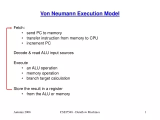
Instruction Cycles The Instruction Cycle • INSTRUCTION FETCH • Obtain the next instruction from memory • DECODE • Examine the instruction, and determine how to execute it • SOURCE OPERAND FETCH • Load source operand • DESTINATION OPERAND FETCH • Load destination operand • EXECUTE • Carry out the execution of the instruction • STORE RESULT • Store the result in the designated destination Not all instructions require all six phases Chapter 4 - The Von Neumann Model
Instruction Cycles The Instruction Fetch Phase • Computer programs consist of sequence of instructions • each instruction = 1-3 Binary Words • stored in memory as 1’s and 0’s • called machine code. • Instructions are fetched from memory using the program counter (PC) as the address of the memory location. • Program counter “increments” for each instruction. Chapter 4 - The Von Neumann Model
Instruction Cycles Instruction Decode Phase • Pick apart the instruction stored in the IR • control unit in control logic does all this • Determines • instruction format • operation • operand sources • operand destination • Combinational logic (ie. Does not require a clock cycle.) Chapter 4 - The Von Neumann Model
Instruction Cycles Source Operand Fetch Phase • Instruction format defines addressing mode • Register mode - Rn • Indexed mode - x(Rn) • Symbolic mode - addr • Absolute mode - &addr • Indirect register mode - @Rn • Indirect autoincrement mode - @Rn+ • Immediate mode - #n • Constant Generator Chapter 4 - The Von Neumann Model
Instruction Cycles Destination Operand Fetch Phase • Instruction format defines addressing mode • Register mode - Rn • Indexed mode - x(Rn) • Symbolic mode - addr • Absolute mode - &addr Chapter 4 - The Von Neumann Model
Instruction Cycles Execute Phase • ALU is combinational logic and does not require a clock • Some instructions are multi-functional and require several operations • PUSH - stack decremented • RETI - status register restored from stack, stack incremented, program counter restored from stack, stack incremented • CALL - stack decremented, program register saved on stack. Chapter 4 - The Von Neumann Model
Instruction Cycles Store Phase • ALU results are stored in register or memory • Location of destination operand is the target of the result of the instruction. Chapter 4 - The Von Neumann Model
Clocks Clocks • With a clock cycle, the processor performs an action that corresponds to an instruction phase. • CPI (Cycles Per Instruction) is the average number of clock cycles required for a microprocessor to execute an instruction. • A microprocessor power is characterized by the number of instructions per second that it is capable of processing. • MIPS (millions of instructions per second) is the unit used and corresponds to the processor frequency divided by the cycles per second (CPI). Chapter 4 - The Von Neumann Model
Clocks Faster Clock Shorter Running Time Faster steps do not necessarily mean shorter travel time. Chapter 4 - The Von Neumann Model
Clocks Basic Clock System Basic Clock Moduleprovides the clocks for the MSP430 devices Chapter 4 - The Von Neumann Model
Clocks Multiple Clocks Chapter 4 - The Von Neumann Model
Clocks Stopping the Clock • Control unit will repeat instruction processing sequence as long as clock is running • If not processing instructions from your application, then it is processing instructions from the Operating System (OS) • To stop the computer, set the CPUOFF bit in the status register (R2) - disables MCLK Chapter 4 - The Von Neumann Model
MPS430 FSM MSP430 Finite State Machine Chapter 4 - The Von Neumann Model
MPS430 FSM Finite State Machine Chapter 4 - The Von Neumann Model
MPS430 FSM Finite State Machine Chapter 4 - The Von Neumann Model
Review Von Neumann In Review • Programs are stored in memory as instructions • instructions are simply collections of 1’s and 0’s • our MSP430 machine has 16-bit instructions • Data is also stored in memory as 1’s and 0’s • A program is executed by • fetching next instruction from memory • decoding it • fetching its operands • doing the requested operation and • storing the result Chapter 4 - The Von Neumann Model
Review The Von Neumann Bottleneck • You may hear of the term “Von Neumann Bottleneck” • All instructions / data has to be fetched from memory • the path to memory is a bottleneck • In spite of this, the Von Neumann model is today’s computing model Chapter 4 - The Von Neumann Model