Download
1 / 44
440 likes | 533 Views
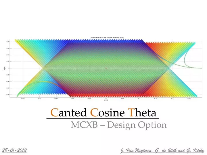
C anted C osine T heta. MCXB – Design Option. 28-01-2013. J. Van Nugteren, G. d e Rijk and G. Kirby. MCXB. Corrector dipole with steerable field direction 2 nested dipoles generate enormous Torque CCT should take forces from windings effectively Requirements

E N D
Canted Cosine Theta MCXB – Design Option 28-01-2013 J. Van Nugteren, G. de Rijk and G. Kirby
MCXB • Corrector dipole with steerable field direction • 2 nested dipoles generate enormous Torque • CCT should take forces from windings effectively • Requirements • 150 mm bore, pre-existing cable • Operating at 50% Ic • Need designs for 1.5 Tm and 4 Tm • Approx1 and 2 m long respectively • Look at Vertical and Horizontal field • V2H2 1.5 Tm / 4.0 Tm • V4H4 1.5 Tm / 4.0 Tm • Decided to focus mainly on 1.5 Tm V2H2 V4H4
A bit of Background • Idea originates from 1969 [1] • Two nested canted solenoids • Axial field components cancel • Dipolar field components add up • Visit ShlomoCaspi LBNL before Christmas • Sparked renewed interest in CCT design • Why now? • Advancements in Rapid Prototyping • Advancements in Computing Cos-Theta [1] Block CCT [1] D. Meyer and R. Flasck, A new configuration for a dipole magnet for use in high energy physics applications, Nuclear Instruments and Methods, no. 80, pp. 339-341, 1970.
Terminology • Repeating pattern (slice) • Coil consists of three basic parts • Spar • Ribs • Cable • Definition of parameters Former
Terminology • Pitch length • Packing factor
Pre-Existing Cable For the designs a pre-existing (MCXB) NbTi cable is available Used Bottura scaling relation for LHC grade conductor Comparing fits: 100% 90% 80% 70% 60% 50% *taken from presentation Mikko 2010
What layer on Which Former? To optimally transfer Torque one Vertical and one Horizontal layer on each former A and B represents the direction of the spiral For insulation between the layers this is not ideal Right now assumed VA-HB-VB-HA layout Pattern can be repeated from here … H-A Former V-B In reality cables under angle H-B Former V-A …
MCXB - V2H2 – 0.9 m 4 layer design Field integral 1.3 Tm without Iron Packing factor = 0.55 2530 A (45°) - 3072 A (0°) at 50% Ic
MCXB - V2H2 – 0.9 m 4 layer design Horizontal and Vertical on same former Top Side Front
MCXB - V4H4 – 0.9 m 8 layer design Field integral 1.9 Tm without Iron Packing factor = 0.55 2530 A (45°) - 3072 A (0°) at 50% Ic 2002 A (45°) – 2438 A (0°)
MCXB - V4H4 – 0.9 m Top Side Front
Skew Angle Influence Ratio Bpeak/Bcen depends on skew angle and # of layers α V2 V4 Without Iron
Field Integral Optimization • Two counteracting processes • Higher skew angle increases Bpeak/Bcen • Lower skew angle increases length of coil ends • Leads to a field integral optimized value for the skew angle V4 V2 All Without Iron
Field Integral Optimization Optimized skew angle depends on coil length V4 V2 0.9 m 1.9 m V4 V2 1.9 m 0.9 m Without Iron
Loadlines Loadlines depend on the angle of the field in the aperture V2H2 100% 90% 80% 70% 60% 50% Without Iron
Directionality – Field Integral • System is coupled • Angular Plot • Angle gives field direction • Amplitude gives field integral • X-coordinate gives horizontal field integral • Y-coordinate gives vertical field integral Without Iron
Directionality – Normal Forces Normal Forces are also angle dependent Maximum force is 7800 N/m For titanium former 3% only of the shear stress V2H2 Without Iron
Directionality - Torque Torque is angle dependent Peak value is 25000 Nm Torque To compare: Glyn’s Mercedes ML has only 616.9 Nm Torque 40.5 X Mercedes ML Without Iron
Torsion , • If the horizontal and vertical layers are not on the same former • Assuming a 10 mm thick solid titanium tube • With only the ends fixed • The stress is then 32.9 MPa • The torsion in the centerwould be ~0.25 deg • Unacceptably high • Conclusion: V-H must be mechanically connected using same or somehow interconnected former(s)
Iron Yoke Field Enhancement • Calculated Iron yoke influence using ROXIE • Long computation times • Non-standard coil for ROXIE • With iron can gain approximately 0.3-0.5 Tm
Comparison Compare specifications per layer with original cos-theta design (note original design has only vertical component) !
Integrated Harmonics ROXIE (high b3?): Without Iron at 2/3r = 50mm ? • Field Code (only noise): at 2/3r = 50mm • Need measurement and perhaps review of codes …
Quench – No Heaters Quench estimation usingcode Glyn Voltage limited to 1 kV Conclusion: need heaters Peak Temperature [K] Too High! Bulk Temperature [K] Current [A] Voltage [V]
Quench – With Heaters Placement for the quench heaters to hit all turns at once in high field area (idea G. de Rijk) Would be able to get entire coil normal in ~8 msafter firing the heaters Tube for heater can be ‘printed’ under ribs inside former
Proposed Steps • First– 0.5 m long 2 layer version (BlueWhale) • Winding test • Field quality measurement • Second – 0.9 meter titanium former, insulated cable, V2 coil which comprises 5/6 components • 1/2 x Former • 2 x Cable • 2 x Outer compression ring • Afterwards– re-optimize the design
Conclusion • Numerical tooling for the design of CCT coils has been developed • Optimized field integrals as function of length for 150 mm free bore coil • Proposed a design for MCXB corrector coils • Can be applied to horizontal and vertical • Needs work • Improved (ROXIE) model with Iron • Assembly technique and Pre-stress on cable • Better stress analysis in tube for the 25000 Nm Torque • Protection • Redesign ground insulation (H-V separation?) • Improve CAD interface for former
MCXB – V2H2 – 4.0 Tm Side Top Front
MCXB – V4H4 – 4.0 Tm Side Top Front
Mathematical Model • Central Spiral [2] • Cable Orientation (at each coordinate) • Direction Vector • Radial vector • Normal vector • Use to create • Strand coordinates • Cable Surface • Cutout Surface [2] S. Russenschuck, Field Computation for Accelerator Magnets. Wiley, 2010.
Field Calculation • Multi Level Fast MultipoleMethod (MLFMM) • Based on algorithm by Greengard and Leslie [3] • Code developed at the University of Twente by E.P.A. van Lanen and J. van Nugteren • Used for the full scale modeling of CICC cables for ITER • Uses GPU using NVIDIA CUDA (or CPU if preferred) • Later adapted for magnetic field calculations (Field) • No Iron:( [3] L. Greengard, The rapid evaluation of potential fields in particle systems, tech. rep., Cambridge, 1988.
BlueWhale demonstrator Coil First study object Testwinding on inside Measure field quality MCBX Cable, 150 mm Bore 45 degree skew angle Low packing factor (0.22)
What is the MLFMM? Grouping the field of many elements in Multipolesand Localpoles Magnetic field of distant elements is approximated using their Multipole Computation times reduced to O(N) instead of O(N2) Note: This is a highly simplified schematic
BlueWhaleFormer Print in clear plastic to see the winding process
BlueWhale Former Already 3D printed some test slices for cable fit testing
Field Integral Optimization and a little on radius (plotted V2 only for 0.9 m) Without Iron x10-2 x10⁻²
Directionality - Current The current at 50% Ic as function of angle. During testing / training the magnet needs to see all directions Without Iron
2D Pseudo Harmonics Coil harmonics as function of axial coordinate Higher harmonics should integrate to zero V2 Dipole Quadrupole Hexapole ...
Quench – With Heaters With quench heaters hitting 70% of coil in 16 ms Peak Temperature [K] Acceptable Bulk Temperature [K] Current [A] Voltage [V]
Quench – No Heaters • 1 kV cable insulation is limiting dump voltage increasing peak temperature • Can improve with: • Cable-ground insulation for ~5 kV • Horizontal Vertical Separation (problem with Torque) • Quench Heater … V-B Former V-A H-B Former H-A …
Quench - Inductances • Need to consider several scenarios • 0, 45 and 90 degrees field angle using inductances and dump resistances for relevant layers only • Inductance matrices (Field Code) Layer 1,3 - 8.65 mH Layer 2,4 - 9.95 mH All layers – 17.6 mH Layer 2,4,6,8 – 44.4 mH All layers – 79.8 mH Layer 1,3,5,7 – 39.1 mH