Download
1 / 15
150 likes | 273 Views
Control and data acquisition system for lower hybrid current drive in Alcator C-Mod. Nils P. Basse in collaboration with J.Bosco, T.W.Fredian, M.Grimes, A.E.Hubbard, N.D.Kambouchev, Y.Lin, B.Lipschultz, R.R.Parker, Y.I.Rokhman, H.Savelli, S.Sherman, J.A.Stillerman,

E N D
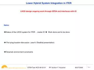
Control and data acquisition system for lower hybrid current drive in Alcator C-Mod Nils P. Basse in collaboration with J.Bosco, T.W.Fredian, M.Grimes, A.E.Hubbard, N.D.Kambouchev, Y.Lin, B.Lipschultz, R.R.Parker, Y.I.Rokhman, H.Savelli, S.Sherman, J.A.Stillerman, D.R.Terry, R.F.Vieira and S.Wukitch • Outline: • Existing control systems • The lower hybrid control system (LHCOSY) • LH tree structure • Data acquisition using the cPCI cards • Coupler camera design • Future work
LHCOSY The program is written in IDL and runs on the Linux machines. The source files can be found here: /home/basse/idl/lhcosy The main program is lhcosy.pro. Additional files needed (at the moment) are on the VMS platform: /user10/basse/idl LHCOSY has a graphical user interface and makes use of widgets: Popup windows where various quantities can be modified. NOTE: This is my first experience with widgets...!
LHCOSY Amplitudes, cart 1
LHCOSY Phases, cart 1
LHCOSY Step-by-step explanation: • Shot number: Default is model shot -1. • Start time and stop time: Klystron amplitude is set to zero beyond those time points. • FIRE button: • Desensitize LHCOSY panel. • Write data to LH tree (amplitude checks). • Initialize, trigger and store cPCI cards. • Sensitize LHCOSY panel • Amplitudes: One window per cart. Calls function cw_wvedit.pro. • Phases: See amplitudes. • Default waveforms: Load default parameters.
LHCOSY Step-by-step explanation (cont’d): • EXIT button. • ACS, TPS, CPS: Plots data acquired using the cPCI cards. • Date & time button: Prints date and time when data was written to shot. • LOAD button: Loads currently selected shot. Design criteria: • Simple to use. • Similar to RF_CONTROL.PRO. • Hard to crash.
LH tree Use traverser to view/edit the LH tree. Currently, the following persons have write access: Joe, Nayden, Ron, Stuart, Josh, Dave and Nils. The children created by Nayden/Josh (ACTION, CONSTANTS, VARIABLES) will not be treated.
cPCI cards We have 13 cPCI cards, 6 chassis in total: • 1 chassis, 2 cards for the ACS. • 3 chassis, 3 cards for the TPS. • Steve has borrowed: 1 chassis, 5 cards (CPS). • Bob will borrow: 1 chassis, 3 cards (CPS). All cards are D-TACQ (www.d-tacq.com), 32 channel, 16 bit, 250 kHz, 128 MB memory. Anti-aliasing filters. One additional card has been ordered for LH, a D-TACQ 16 channel, 16 bit, 10 MHz, 1 GB memory. My idea is to use this card to acquire from some of the forward/reverse power detectors. The coupled power is an indirect measure of edge density fluctuations.
Camera Bruce and Brian have a visible light camera (plus a fiber) in a re-entrant tube in K-port. This has been observing the limiter between G- and H-ports. This camera could probably be rotated to observe the coupler, which is to be installed in C-port. Bruce helped me clean the tube (quartz window opaque), we put it and the camera back in. Rotating the camera about 180 degrees, a partial view of C-port was obtained. Henry is designing new camera/filter holders – the angle has to be changed about 10 degrees.
Camera • Coupler in C-port [yellow] • Camera field-of-view is 26 degrees [green] • Camera center line [blue] • The camera looks 10 degrees beyond the coupler end; due to tilt of view, since camera is looking up at C-port.
Future work • Complete the LHCOSY program. • Complete the User’s Guide. • Complete camera design, re-install camera, check that acquisition works. • Once ethernet is established at the TPS racks, add those cPCI cards to the LH tree and LHCOSY. • Handshaking of IDL vs.Matlab/Opal-RT/Labview with Joe and Yuri. This presentation and the current version of the User’s Guide are available at http://www.npb.dk/lhcd/lhcd.html