Download
1 / 66
660 likes | 825 Views
First lab reports. Grading Explanation of “soft windows” in upper right corner and how mouse is used to change entities therein: 5 points Adjustment of gun tilt and gun shift: 3 points Need for diagram of sample locations: 2 points Other details: 15 @ 1 point 25 point total

E N D
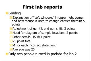
First lab reports • Grading • Explanation of “soft windows” in upper right corner and how mouse is used to change entities therein: 5 points • Adjustment of gun tilt and gun shift: 3 points • Need for diagram of sample locations: 2 points • Other details: 15 @ 1 point • 25 point total • -1 for each incorrect statement • Average was 20 • Only two people turned in prelabs for lab 2
Meeting place update • Monday classes: WEB 103 • Friday classes: WEB 112
Currents in an SEM (W-filament) • Filament current: Current that heats a tungsten filament, typically 2.6-2.8 A. Strongly affects filament lifetime. Similar for Schottky FEG, but only heated to 1700 K • Emission current: total current leaving the filament, typically about 400 μA for W-filament, 40 μA for FEG. • Beam current: Portion of emission current that transits the anode aperture; decreases going down the column. • Probe current: a calculated number related to the current on the sample, typically 10 pA – 1 nA. • Specimen current: the current leaving the sample through the stage, typically about 10% of the probe current. Remember that one electron incident on the sample can generate many in the sample…a 20 keV electron can generate hundreds at 5 eV. • FEI also defines a parameter called “spot size” which is proportional to the log2(probe current); proportionality constant depends on aperture size.
Surface Emissions Pole Piece, etc SE3 X-rays Cathodoluminescence • ≈ 1 nm for metals up to 10 nm for insulators Specimen current
Interaction volume • The interaction volume falls with beam energy E as about 1/E5 • (dE/ds ~ [ln(E)]/E) • The interaction volume no longer samples the bulk of the specimen but is restricted to near-surface regions only • The signal is therefore much more surface oriented at low energies than at high Monte Carlo simulations of interactions in silicon
What happens at low energy? • At low energies the electron range falls from the micrometer values found above 10keV to just a few nanometers at energies of 0.5keV • This variation has profound implications for every aspect of scanning microscopy Range from modified Bethe equation
Spatial resolution….. • At high energy the SE1 signal typically comes from a volume 3-5nm in diameter, but the SE2 signal from a volume of 1-3µm in diameter • High resolution contrast information is therefore diluted by the low spatial resolution SE2 background SE2 come from the full width of interaction volume
But at low energies…... • ..the SE1 and SE2 electrons emerge from the same volume because of the reduction in the size of the interaction volume • So SE1, SE2 and BSE images can all exhibit high resolution…. the interaction volume shrinks
Seeing is believing • The sample is a 30nm film of carbon on a copper grid • At 20keV the carbon film is transparent because it is penetrated by the beam.The SE signal comes from the carbon film but is produced by electrons backscattered from the copper SE image of TEM grid 20keV
Electron range at low energy • Carbon film completely covers grid!! • At 1keV -by comparison - the carbon appears solid and opaque because the beam does not penetrate through the film • This variation of beam range with energy is dramatic and greatly affects what we see in the low voltage SEM Same area as before but 1keV beam
Some consequences of low energy operation • The interaction volume decreases in size and shrinks towards the top surface as the energy falls
High Energy Images • At high energies the beam travels for many micrometers giving the sample a translucent appearance • The SE image information is mostly SE2 and so copies the BSE signal. • The information depth is ~Range/3 and so is often a micron or more MgO cubes 30keV S900
Low Energy Images • At low energy the beam only penetrates a few tens of nanometers. • The image now only contains information about the surface and the near surface regions of the specimen • The signal information depth (SE1,SE2 and even BSE) is only nanometers 0.1µm Silver nanocrystals 1keV
as a result. . . . the SE signal (in the LVSEM can produce) • high contrast • nm resolution • easy to interpret surface images from crystals & nano-particles… Indium Tin Oxide (ITO) Silver Nanocrystals 1keV
and .. ….organics such as polymer resists
The best approach - try a wide range of energies and modes CNT with intercalated iron
Some consequences of low energy operation • Spatial resolution is improved in all image modes
Low Voltage BSE imaging • At a WD of 1.5 or 2mm high resolution BSE imaging is readily possible and is very efficient • ‘Z’ contrast may be less evident at low energies than at high Ta barrier under copper seed
Some consequences of low energy operation • Changes in SE and BSE generation lead to differences in image detail and interpretation
SE yield variation • The rapid change in the incident electron beam range causes a large, characteristic variation in the SE yield • Typically the yield rises from ~0.1 at 30keV to in excess of 1 at around 1keV, and as high as 100 for some materials Experimental SE yield data for Ag
Why the SE yield changes • SE escape depth is ~ 3-5nm • At high energies most SE are produced too deep to escape so the SE yield d is low • But at lower energies the incident range is so small that most of the SE generated can escape so the SE yield rises rapidly • At very low energies fewer SE are produced because less energy is available so the SE yield falls again low voltage high voltage interaction volumes
BS yields at Low Voltage • The BSE yield h varies with energy as well as with atomic number • Above ~2keV the yield rises steadily with Z • But at low energies the BSE yield for low Z elements rises, and for high Z elements it falls • Below 100eV the situation is more complex Experimental BSE yield data
Do high and low kV SE images look the same? • No..compared to the high energy norm… • The image looks less 3-D • Highlighting is absent • Surface junk is more visible • Interpretation is essential Device images at 20keV and 1keV
Origin of topographic contrast • Topographic contrast weakens and ultimately disappears as the beam energy is reduced. SE escape At high energy tilting the sample puts more of the interaction volume in the SE escape zone But at low energy all the SE always escape
Beam penetration effects SE emission • At high energy the interaction volume fills features on the surface - SE2 emission leads to enhanced SE emission making objects look almost 3-dimensional • But at low energies the reduced interaction volume means that only the edges of features are enhanced High energy Low energy
Some consequences of low energy operation • Less charge is deposited in the sample • This is the real advantage of a FEG over a W-filament: FEG has almost as much resolution at 1 kV as at 15 kV • FEI now has landing energies as low as 50 eV!!!
The LVSEM and charging • When electron beams impinge on non-conducting samples a charge can build up inside the specimen which can make SEM imaging unstable, difficult, or even in extreme cases, impossible • By operating at low beam energies this problem can often be minimized or eliminated • Low voltage SEM has now become the norm for many users because of this effect Pathological charging artifacts
Charge Balance Electrons cannot be created or destroyed so currents at a point sum to zero (Kirchoff’s Law) Where h, d are the BSE and SE yields respectively, and Q is the charge on the specimen at some time t. For a conductor this equation is always balanced by Isc
Working with Conductors • If the sample is a conductor then it cannot charge and Q=0 at all times • In this case at high energies where electron yields are small excess current flows to ground as specimen current ISC • At low energies where yields are high current flows from ground to make up the deficit • But the charge is always balanced and stable imaging is possible
..but in an insulator • ISC is zero • If the sample is not to charge then • This is achieved when This condition represents a dynamic charge balance If (h+d)<1 then negative charging will occur and If (h+d)>1 then positive charging will occur
The charge balance condition • The variation of the () yield curve is about the same for all materials • In most cases there are energies for which () = 1 • These are called the E1 and E2 or ‘crossover’ energies Positive charge NEUTRAL Negative charge Total yield data for quartz (SiO2)
E1 and E2 values for pure elements • E1 and E2 both increase with atomic number Z • E2 may also depend on the density (e.g diamond, graphite, and dry biological tissue have very different E2 values) • A few elements never reach charge balance (e.g Li, Ca) • Low Z elements need low keV. Since these elements so important the goal has been to make SEMs work at 0.5 - 2keV Computed E1 and E2 energies
E2 values Material E2(keV) Material E2 (keV) Resist 0.55 Kapton 0.4 Resist on Si 1.10 Polysulfone 1.1 PMMA 1.6 Nylon 1.2 Pyrex glass 1.9 Polystyrene 1.3 Cr on glass 2.0 Polyethylene 1.5 GaAs 2.6 PVC 1.65 Sapphire 2.9 PTFE 1.8 Quartz 3.0 Teflon 1.8
Determining E2 in the SEM Negative E>E2 Positive E<E2
Charging in Complex materials • In the case of complex materials (e.g. layered) then the charge balance must be considered separately for each component • If a beam penetrates a layer then it will charge positively (net electron emitter). The E3 energy at which this first occurs is typically <1keV for 3nm of hydrocarbon, and a few keV for a 250nm thick passivation layer. BS SE substrate
Thin film charging (E3) SE Image of Chip covered by a 1mm passivation layer imaged at 15keV - above the E3 energy How a thin metal film on top of an insulator charges with energy
On a new SEM this will be the lowest available energy On older machines you must decide how low to go before the performance becomes too poor to be useful for the purpose intended The goal is to avoid implanting charge deep beneath the surface. If this is allowed to occur then stable imaging may never be achieved. Step #1 - Set the SEM to the lowest operating energy Imaging non-conductors
Failure to follow this advice... • If a poorly conducting sample is irradiated with a high energy beam then the implanted charge may prevent a low energy beam from reaching the surface at all • In that case it acts as a mirror giving a birds’ eye view of the inside of the SEM Mirror image of sample chamber in an SEM
If the sample is charging positively (i.e. a dark scan square) then E1< E<E2 or E>E3. Increase the beam energy and proceed to image If sample is charging negatively (i.e. bright scan square) then E>E2. Since we cannot reduce the beam energy any further we go on to step 3. Step #2 - Determine the charging state of the sample using the scan square test Next……...
Step 3 • Tilt the sample to 45 degrees and repeat the usual scan square test • Can E2 be reached now? • E2() = E2(0)/cos2 so tilting by 45 degrees raises E2 by a factor of 2x • But ..because E2 varies with the angle of incidence the ‘no charge’ condition can never be satisfied everywhere on the surface at the same time and charging will always occur Tilting the sample reduces charging at all energies
So does charge balancing help ? • In some cases - yes • But because the E2 ‘charge balance’ condition can never be simultaneously satisfied everywhere on a surface with topography - hence charging will always be present Phase Shift Lithography mask slow scan imaged at E2
Fast scan Potential Slow scan Beam dwell time on pixel TIME A better strategy • Go to E2 and then scan at high rates • The sample acts like a leaky capacitor which charges more quickly than it discharges • At slow scan speeds each pixel charges and then discharges before the beam reaches it again • this fluctuating potential affects SE emission, signal collection, scan raster etc • At high scan speeds (TV) there is less time to discharge so the potential stabilizes Forget eliminating charge – stabilize it then live with it
Scan stabilized imaging IB=100pA Vacc. : 1.5kV Mag. : x200k Imaged at E2 and scanned at TV rate Uncoated photoresist
the choice of detector Single polymer macro-molecules ET lower detector SE + BSE + scattered electrons Pure SE signal – Thru-lens upper detector
makes a difference Uncoated Teflon tape adhesive BSE image at 2keV
..so does reducing IB • the charging varies directly with IB so reducing the current cuts the charge • Use a smaller aperture, or reduce the gun emission current • Reduces the S/N ratio so longer scan times may be required
..and lowering the magnification • This minimizes Dynamic Charging (internal charge production from electron-hole pairs). The magnitude of this depends on the dose and hence on the magnification • Dynamic charging is worst when E0 is close to E2 • Limits resolution by limiting magnification
Choosing a detector • The choice of detector can have a significant effect on the apparent severity of charging • The conventional ET (Everhart - Thornley) detector sees more topography but is much less sensitive to charging than... Individual polymer macro-molecules on Si at 1.5keV -Lower (ET) detector
Upper detector • …a through the lens detector. This is because TTL systems act as simple SE spectrometers and preferentially select low energy electrons • Note however that charging can be a useful form of contrast mechanism when properly employed Same area as before, TTL detector
Comparing upper and lower detectors In-Lens Detector – Chemistry Image Side Detector - Topography What is this residue?? Missing CoSi!! SiO2 Poly2 with CoSi on Top rougher Si substrate with CoSi2 smoother