Download
1 / 27
281 likes | 682 Views
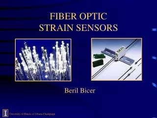
Fiber laser hydrophones as pressure sensors. P. E. Bagnoli, N. Beverini, E. Castorina, E. Falchini, R. Falciai, V. Flaminio, E. Maccioni, M. Morganti, F. Sorrentino, F. Stefani, C. Trono Dipartimento di Fisica “E. Fermi” Pisa Istituto di Fisica Applicata “ Nello Carrara”, IFAC-CNR

E N D
Fiber laser hydrophones as pressure sensors P. E. Bagnoli, N. Beverini, E. Castorina, E. Falchini, R. Falciai,V. Flaminio, E. Maccioni,M. Morganti, F. Sorrentino, F. Stefani, C. Trono Dipartimento di Fisica “E. Fermi” Pisa Istituto di Fisica Applicata “ Nello Carrara”, IFAC-CNR INFN Sez. Pisa Dipartimento di Ingegneria dell’Informazione - Pisa
SUMMARY • What is a Fiber Bragg Grating (FBG) • What is a Distributed Bragg Reflector Fiber Laser (DBR-FL) • Fiber Laser sensor working principle • Fiber laser as acoustic sensor (hydrophone) • Future R&D • Conclusions
FIBER BRAGG GRATINGS WHAT IS A FBG: a periodic perturbation of the core refractive indexof a monomode optical fiber. HOW DOES IT WORK:when the radiation generated by a broad source is injected into the fiber and interacts with the grating, only the wavelength in a “very narrow band”(~0.2 nm) can be back-reflected without any perturbation in the other wavelengths. If the grating pitch is , and the core effective refractive index is neff, the resonance condition is given by: Bragg = 2neff A FBG is a narrow-band mirror
FBG LASER FABRICATION TECHNIQUE FBGs reflectors are fabricated in our labs by using the phase-mask technique. A phase-mask is a diffractive optical element, which spatially modulates the UV writing beam (typically at = 248 nm, where the photosensitivity of the fiber is at its best). The near-field fringe pattern, which is produced behind the mask, photo-imprints a refractive index modulation on the core of the photosensitive fiber. The grating pitch depends on the phase-mask pitch M (= M/2)
THE DISTRIBUTED BRAGG REFLECTOR FIBER LASER (DBR-FL) Two Bragg gratings with identical reflection wavelength directly inscribed on an erbium doped (active medium) optical fiber. This structure forms a Fabry-Perot laser cavity which, when pumped at 980 nm, lases with emission at ~1530 nm
ERBIUM ION ENERGY LEVELS Three level laser system
TYPICAL AMPLIFIED SPONTANEOUS EMISSION SPECTRUM OF AN ERBIUM DOPED OPTICAL FIBER Amplified spontaneous emission Laser cavity longitudinal modes FBG reflection spectrum A cavity enclosed between two mirrors forms an optical resonator. Only a discrete set of resonant longitudinal modes can be allowed. Bragg gratings reflectivities and cavity length are choosen in order to select a single stable longitudinal mode.
Effect of the lasing: single stable longitudinal mode + very narrow linewidth laser < 4*10-8 nm (Bragg = 0.2 nm) Fiber laser linewidth: < 5 kHz Coherence length > 50 km
FIBER LASER TYPICAL CHARACTERISTICS • ED Fiber characteristics • ED fiber absorption @ 980 nm: 14 dB/m • ED fiber absorption @ 1530 nm: 18 dB/m • FL characteristics • Bragg reflectors length: 1cm • Rear FBG reflectivity: >99% • Output FBG reflectivity: ~ 90% • Cavity length (distance between gratings): 1-3 cm • Optical power emitted: 500 W – 2 mW (pump power 300 mW) • Stable single longitudinal mode
DBR FIBER LASER Photo of one of several DBR lasers realized. The green light is due to “up conversion” (collision of two erbium ions with energy jump at higher levels). The ED fiber is cut and spliced to a standard fiber (low loss <0.3 dB/Km) very close to the cavity.
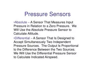
FIBER LASER SENSORS Physical elongation (strain), temperature and pressure variations, which changes the FBG pitch ,the cavity length, and fiber refractive index neff, produce a shift in the fiber laser emission line. TYPICAL SENSITIVITIES FOR A BARE FIBER LASER STRAIN [] ~1.2 pm/me @ 1550 nm PRESSURE ~ -4.6 pm/MPa @ 1550 nm TEMPERATURE ~ 10 pm/°C @ 1550 nm
ADVANTAGES • Intrinsic safetyand immunity from electromagnetic fields • the fiber is realized entirely with dielectric materials (glass and plastic) • Very low invasivity • very small dimensions of the optical fiber (~ 125 m) • ED fiber is compatible with standard telecom fibers (very low signal attenuation ~0.3 dB/km) • the optoelectronics control unit can be placed several km far from the measurement point
ADVANTAGES FBG reflects the light in a narrow band: possibility of multiplexing for a quasi-distributed measurement configuration, by using a single pump and a single interrogation system Several lasers (an array of hydrophones) can be “written” on the same optical fiber Optical Spectrum Analyzer 0.1 nm optical resolution
FL HYDROPHONE EXPERIMENTAL SETUP The pump and laser radiations travel both into the core of the ED optical fiber. The WDM coupler acts the spectral separation and the optical isolator avoid unwanted feedback into the cavity. The acoustic wave produces the modulation of the laser wavelength. The interferometer converts wavelength modulation into a phase-shift.
MACH-ZENDER INTERFEROMETER (MZI) Quadrature detection The laser signal is splitted and then recombined thus obtaining a signal proportional to a raised cosine function at the MZI output. The phase depends on the laser frequency c/ (which depends on the acoustic signal) and on the Optical Path Difference (OPD). The MZI is locked, at low Fourier frequencies (< 5 kHz), at one side of a fringe in the middle point, where the sensivity has its maximum value,by using a servo loop that acts on the length of one arm of the interferometer by stretching the fiber through a piezoelectric actuator.
DETECTION APPARATUS SENSITIVITY Proportional to It depends from the laser emission power, the OPD, and the emission wavelength (Pascal)
FIBER LASER VS. CONVENTIONAL HYDROPHONE Calibration of the first developed single mode FL (10 W output power) September 2004 Response to loud-speaker amplitude modulation at 16.625 kHz The fit is very good
FIBER LASER VS. CONVENTIONAL HYDROPHONE Response to a sinusoidal acoustic signal (60 KHz) 100 W output power; OPD=15m Spectrum Analyzer bandwidth: 125 Hz
FIBER LASER VS. CONVENTIONAL HYDROPHONE Response to a sinusoidal acoustic signal (60 KHz) 100 W output power; OPD=15m Spectrum Analyzer bandwidth: 125 Hz
FL DEPENDENCE FROM ACOUSTIC FREQUENCY Output power: 600 W Not completely understood fenomenum.
FL DEPENDENCE FROM ACOUSTIC FREQUENCY EFFECTS OF THE ACOUSTIC WAVE ON THE DBR-FL The wavelength of a 50 KHz acoustic signal in water is 3 cm Comparable with the laser cavity and FBG length Power modulation of the laser emission, induced by the acoustic signal, is superimposed to the wavelength modulation The sensitivity of the FL+MZI depends greatly on the frequency
FL DEPENDENCE FROM ACOUSTIC FREQUENCY ENVIRONMENTAL AND EXPERIMENTAL SETUP DRAWBACKS The PZT loud-speaker is not calibrated and is driven with sinusoidal continuous wave (no short pulse source at present). No time domain analysis The water tank has finite (small) dimensions: ~ 1m3 It’s impossible to discriminate the direct acoustic waves from the reflected waves. The mechanical frame is not optimized.
POSSIBLE IMPROVEMENTS Recoating of the fiber Increase the FL pressure sensitivity Flats the frequency respons
FL RECOATING Cylindrical recoating (6 mm x 100 mm) of the fiber with epoxy resin
FUTURE DEVELOPMENTS • Flat emission loud-speaker • Time domain signal acquisition (ADC sampling @ 1 MHz) • Sensor calibration in a wide tank (equipped pool) • Sensor test at high pressure (300 Atm) • Production of a bipolar acoustic signal (-like) • Study of the FL mechanical frame • Measurements of directional sensitivity • Tests in ice • Many sensors on the same fiber (multiplexing)
CONCLUSIONS • We have the technology for producing DBR Fiber laser • We have developed the apparatus for acoustic wave detection in water • The comparison with conventional hydrophone showed a very good fit between the two sensors • The FL sensitivity is better than that of the standard hydrophone, but depends on the acoustic frequency • The fiber laser based technology seems to be adequate for neutrino acoustic detection in water (in ice?)