Download
1 / 10
100 likes | 100 Views
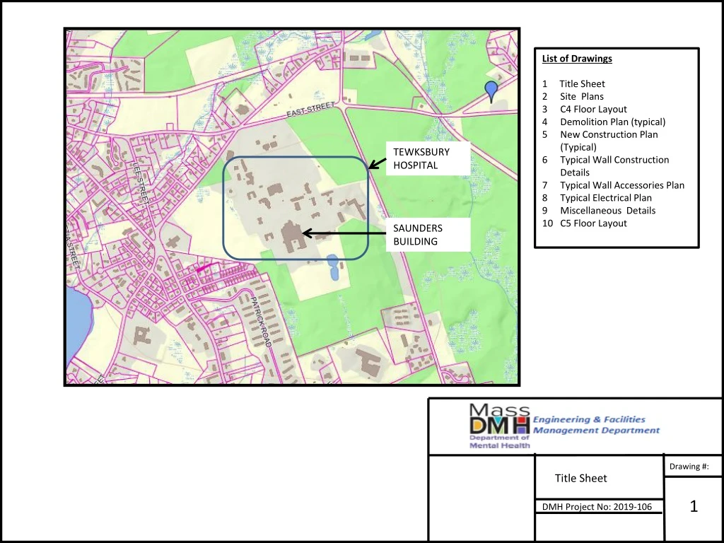
This set of drawings includes site plans, floor layouts, demolition plans, new construction plans, wall construction details, electrical plans, and miscellaneous details for the C Wing renovation project at Tewksbury Hospital's Saunders Building.

E N D
List of Drawings 1 Title Sheet Site Plans C4 Floor Layout Demolition Plan (typical) New Construction Plan (Typical) Typical Wall Construction Details Typical Wall Accessories Plan Typical Electrical Plan Miscellaneous Details C5 Floor Layout TEWKSBURY HOSPITAL SAUNDERS BUILDING Drawing #: Title Sheet 1 DMH Project No: 2019-106
C Wing Location of “C” wing Aerial photograph of the Saunders Building Drawing #: Site Plan 2 DMH Project No: 2019-106
Room #061 Room #060 Room #056 Room #035 Room #034 Room #040 Note: Rooms 061, 060, 056, 035, 034, and 040 are the rooms where the work will occur. Drawing #: C4 Floor Layout 3 DMH Project No: 2019-106
Remove existing tile & CMU needed for installation of new door frame Remove existing light switch DEMOLITION NOTES Cut existing tile and CMU at new door frame locations to inside dimension of frame. Cut interior and corridor tile back to edge of frame. Cut existing interior title at proposed connection to new wall assembly. Remove and properly store existing fixtures and smoke detectors. Disconnect heating unit and remove required components to allow new wall assembly to be flush with existing window mullion. Remove existing lighting wall switch at pipe chase. Remove existing tile needed for installation of new wall Remove existing light fixtures and smoke detector Remove existing heating system needed for installation of new wall Legend smoke detector 1’ x 4’ lighting fixture heating unit mullion in window glass Drawing #: Typical Demolition Plan 4 DMH Project No: 2019-106
Cover existing light switch opening with epoxy-painted 12 GA. Steel covers. New Door Frame New Light Switches (one double switch per bedroom) New Wicket Doors New Lighting Fixtures New Smoke Detectors New Thermostat (one per bedroom) New Gypsum Wall Assembly New Night Lights (two per bedroom) Drawing #: Typical New Construction Plan 5 DMH Project No: 2019-106
2” to 6” CEILING SLAB Steel Stud Fire Stop Track w/ fasteners 24 in. o.c. max 4” CMU Tile Wall Assembly At Corner Direct Furring Strip 5/8” Gypsum Panel 25-ga. 3-5/8” metal studs 16”o.c. Isolation strip Window Mullion Wall Assembly At Window Mullion Wall Assembly At Corridor Wall Thermafiber Sound Attenuation Blankets (SAFB) 5/8” Plywood Bottom rail w/ fasteners 24 in. o.c. max FLOOR SLAB Drawing #: Typical Wall Construction Details 6 DMH Project No: 2019-106
WALL ACCESSORIES NOTES • Three 1’ x 1’ plastic access panels are to be installed in six of the bedrooms providing access to the electrical and smoke detector junction boxes. • One new light switch shall be installed in each bedroom and shall be approximately 3’ from interior side of corridor wall. • Two night lights shall be installed in each bedroom with a switch connection at the lighting switch location. Night lights shall be installed at approximately 8’ and 16’ from interior side of corridor wall. • One new thermostat shall be installed in each bedroom. Thermostat shall be installed at approximately 12’ from interior side of corridor wall. 8’ - 9” 5’ -0” 2’ -0” Legend night light (recessed) Lighting switch (recessed) Thermostat (recessed) access panel (surface mount) Drawing #: Typical Wall Accessories Plan 7 DMH Project No: 2019-106
New surface mounted wiremold Existing Electrical Layout Proposed Electrical Layout Legend night light (recessed) Smoke Detector (Surface Mounted) Thermostat (recessed) 1’ x 4’ surface mounted light fixture Existing Junction Box Drawing #: Typical Electrical Plan 8 DMH Project No: 2019-106
Metal Door Frame Detail Drawing #: Miscellaneous Details 9 DMH Project No: 2019-106
Room #061 Room #060 Room #056 Room #035 Room #034 Room #040 Note: Rooms 061, 060, 056, 035, 034, and 040 are the rooms where the work will occur. Drawing #: C5 Floor Layout 10 DMH Project No: 2019-106