Download
1 / 8
80 likes | 83 Views
E90 Midsemester Report. Aron P. Dobos 20 March 2006. stimulus. TDR. reflection. ampl. dist. Time Domain Reflectometer. Measurement device for cable characterization and testing

E N D
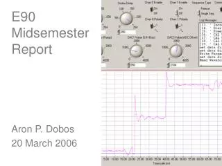
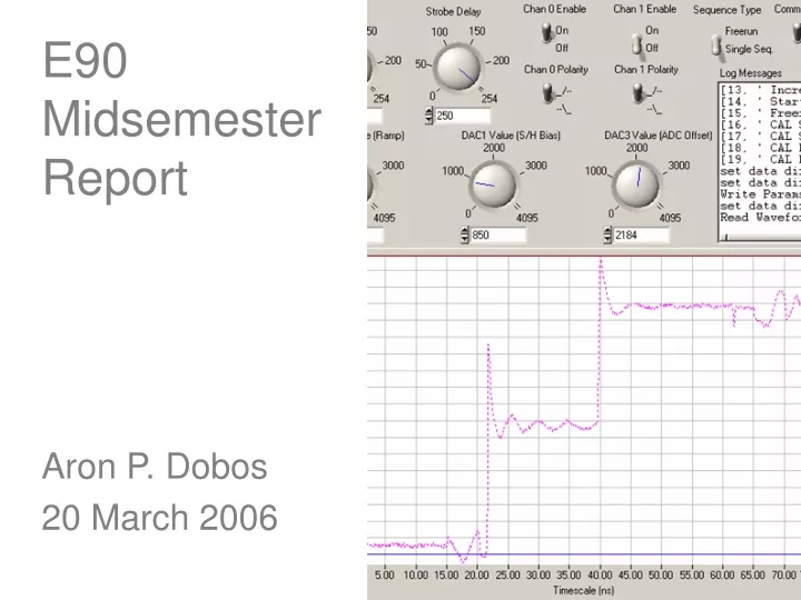
E90MidsemesterReport Aron P. Dobos 20 March 2006
stimulus TDR reflection ampl. dist. Time Domain Reflectometer • Measurement device for cable characterization and testing • Instrument sends a pulse of energy down the test cable and measures the reflections from any discontinuities in the cable • Results are reported as an amplitude vs. time (or distance) waveform
PC Host Interface (Parallel Port) ADuC7026 (ADC, DAC, SPI, GPIO) TDR (Timebase, Step gen., Sampler) test cable Implementation • Implementation based around the Analog Devices ADuC7026 microcontroller • TDR acquisition circuit with step generator, timebase circuit, sampler • Interfaces to host PC through the parallel port
Hardware -Circuit built with Surface Mount Technology (SMT) components to minimize parasitic effects -4 layer PCB used to facilitate proper high frequency grounding and supply routing -Two copies of the TDR circuit have been built -TDR circuit plugs into the standard ADuC7026 development board for simplicity
Testing • High speed equivalent-time sampling oscilloscope (20 GHz+ bandwidth) required for accurately measuring rise/fall times of the pulse generator and sampling circuit • Special hardware pretrigger output implemented to trigger the Tektronix 11801 scope • Realtime 100 or 500 MHz scope used for testing and calibrating the timebase
Software • PC host control software written using CVI provides access to the debugging functions but does not yet provide a useful interface for making TDR measurements • Microcontroller (ADuC7026) software has been written with extensive debugging facilities but just basic waveform acquisition capabilities • Xilinx FPGA-based timebase circuit VHDL code works but must be expanded to control additional hardware resources
Tasks • -Rewrite embedded timebase controller software and PC host interface for usability • Clean up waveform aberrations if possible by tweaking the sampler circuit • Decrease minimum data point spacing from 25 ps to 12.5 ps or perhaps even more