Download
1 / 60
620 likes | 775 Views
AAE451 Conceptual Design Review. Team 2. Chad Carmack Aaron Martin Ryan Mayer Jake Schaefer Abhi Murty Shane Mooney Ben Goldman Russell Hammer Donnie Goepper Phil Mazurek Chris Simpson John Tegah. Conceptual Design Outline. Mission Summary Concept Summary Best Design

E N D
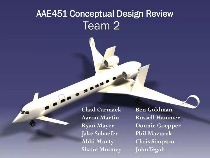
AAE451 Conceptual Design Review Team 2 Chad Carmack Aaron Martin Ryan Mayer Jake Schaefer AbhiMurty Shane Mooney Ben Goldman Russell Hammer Donnie Goepper Phil Mazurek Chris Simpson John Tegah
Conceptual Design Outline • Mission Summary • Concept Summary • Best Design • Advanced Technologies Review • Sizing Code • Engine Modeling • Aerodynamics • Performance • Structures • Stability and Control • Noise • Cost • Summary
Mission Statement To be the primary systems integrator of a high speed, long range executive transport system with unprecedented efficiency and minimal environmental impact.
Design Mission 2 3 7 6 Alternate Los Angeles Hong Kong 0 1 4 5 8 9 0-1: Take off to 50 ft. 5-6: Climb to 5000 ft. (Best Rate) 1-2: Climb to 41000 ft. (Best Rate) 6-7: Divert to Alternate 200 nm 2-3: Cruise at Mach 0.85 7-8: 45 minute Holding Pattern 3-4: Decent to Land (No Range Credit) 8-9: Land 4-5: Missed Approach (Go Around) 7100 nm 200 nm
Aircraft Concept Walk-Around • Noise Shielding • Vertical Stabilizers • Lifting Canards Circular Fuselage • Fuselage – aft • Mounted Engines Noise Shielding Low Wing Spiroid Wing-Tips
Lifting Canard Pros Cons Designed to provide more lift at high speeds Reduces induced drag at cruise May allow for smaller main wing Downwash from canards has large effect on main wings Stability demands that canard stall before main wing, therefore main wing never reaches full lift potential
Canard & N+2 • The canard design had a smaller empty weight, but had a larger fuel burn which implies worse total drag performance
Vertical Stabilizer • Two vertical stabilizers are placed directly on the wings to shield the engines. The intent was to reduce the noise signature of the aircraft.
Engine Mounting • Two engines mounted in rear of the fuselage for reliability and thrust requirements • The benefit of mounting the engines above the wing and surrounded by vertical stabilizers will keep noise levels low.
Cabin Considerations • Stand up cabin in the aisle to accommodate the “plush” comfort level • Crew areas expanded to allow sleeping quarters for reserve pilot • Two lavatories and galley necessary for full passenger load
Summary of Advanced Concepts • Geared Turbofan • 15% reduction in fuel burn • Noised lowered to approximately 20 dB below stage 4 • 50% below CAEP-6 emissions • Composites • 20% reduction of structural weight • Spiroids
Spiroid Wingtips • 6-10% drag reduction in cruise flight • Yielded a 10% improvement in fuel burn • Installed on more than 3,000 aircraft, including several business jet types, as well as the Boeing 737 and 757 airliners • Aid the US Federal Aviation Administration in increasing airspace capacity near airports • Potential for large decreases in wake intensity. This could substantially alter the requirements for separation distances between lead and following aircraft in airport traffic patterns http://www.flightglobal.com/blogs/flightblogger/2008/06/spiroid-wingtip-technology-the.html
MATLAB Code Flowchart Initial Guess Wo Geometry Calculations We Prediction Wfuel Prediction Engine Model Drag Calculation Set W0 guess to W0 calc W0 Calculation W0 = W0 calc
Calibration Factors • Calibrated Canard design to Beechcraft Starship
Technology Factors • Composites reduced structural weight by 20% • Spiroids reduced SFC drag by 10% • Canards reduce induced drag (assume 5-10%) • Geared turbofan reduced fuel burn (SFC) by 15%
Carpet Plots - Conventional • Best AR = 10 => W0 = 76000 lbs • Limited by top of climb (100 ft/min @ 41k ft) and takeoff distance (4000 ft)
Carpet Plots - Canard • Limited by top of climb (100 ft/min @ 41k ft) and takeoff distance (4000 ft)
Canard Sizing Summary • AR = 12 • T/W = .34 • W0/S = 87 • W0 = 71,300 lbs • Wempty = 38,000 lbs • Wfuel = 31,500 lbs • Landing ground roll = 2200 ft • Takeoff ground roll = 3900 ft
Drag Prediction • Component drag build up based on four types of drag • Drag: pressure, induced, miscellaneous, and wave • Components: pylons, engines, fuselage, wings, etc. • Induced drag is a sum of that produced by both the main wing and canard, with the canard contributing its own downwash onto the main wing • Viscous effects are not strong enough to damp out the downwash over the distance between the canard and main wing
Drag at Cruise • CD = kCD,p + TF*CD,i + CD,misc + CD,w • = 1.05CD,p + TF*CD,i + CD,w • = 0.01661 + 0.01002 + 0.00002 • CD,cruise = 0.02665
Wing Airfoil Selection • Required Cl • Takeoff: 1.2 • Cruise: 0.46 • Landing: 2.0 • Supercritical Airfoil use • Comparison of RAE 2822 to NASA SC(2)-0610. • NASA airfoil would provide higher lift but have a greater moment. • NASA SC(2)-0610 selected for wing design. • Geometry and comparison from http://www.worldofkrauss.com/
Flap Selection • Regular flap vs Single slotted Flap • Higher lift, but more complex • Can meet required lift of 2.0 with only single slotted flap • http://ntrs.nasa.gov/archive/nasa/casi.ntrs.nasa.gov/19750064451_1975064451.pdf
Tail airfoil Selection • Small operating range for angles of attack. • Laminar flow foil selected to reduce drag. • Symmetrical airfoil. • NACA 64(2)-015 was selected for use.
Canard airfoil • Symmetric Supercritical airfoil was desired for the canard
Engine Modeling • Engine Deck similar to CF-34 • Generated with ONX/OFFX • Scaled From Data Sheet • Based on required thrust
Engine Description • Geared Turbofan • Sea Level Static Thrust: 11,900 lb • Bypass Ratio: 12:1
Mission Modeling • Calculated fuel weight for individual mission segments 2 3 7 6 25200 lbs 2700 lbs 1350 lbs 1400 lbs 0 1 4 5 8 9 130 lbs 280 lbs 250 lbs 125 lbs 280 lbs 7100 nm 200 nm
V-n Diagram • Aircraft limited by Clmax at low speeds and by the structure at high speeds • Design speed for max gust same as cruse speed due to Clmax at altitude • Maneuver load factor • nmax = 2.5 • nmin = -1 • Gust load factor • ns_max = 2.63 • ns_max = -1.13 • Dive Mach • Md= .87
Payload Range Diagram *Mach = 0.85 Altitude = 41,000 feet Still air range
Structural Overview Fillets Pylons Supported by Bulkheads/ Beams Landing Gear Supporting Structure Frames Door Sills Window Sills Fillets Fillets Shear Webbing Main Spar Longerons Fillets
Material Selection Process • Static Dissipation and Electrically Conductive • Icephobic Coatings • Maintenance • Cost • Density and Fatigue Resistance
Materials • Silicones • Ability to maintain its elasticity and low modulus over a broad temperature range provides excellent utility in extreme environments • Protection against static accumulation and discharge • Composites • Light and very strong but maintenance is an issue and is expensive • No Established data • Aluminum • Lower cost • Easier certification • Established maintenance • Steels • Used mainly in the landing gear • Advanced Alloys • Higher elastic modulus • Density savings
Aircraft Components • Fuselage skins and wing stringers - Aluminum Alloys • Better Fatigue Crack Growth (FCG) performance reduces structural weight. • Canard, Control surfaces and wing skin panels – Glare Composites • Resistant to damage at high temperatures • Landing gear – Steel Alloy • High strength, corrosion resistant • Nose, Leading and Trailing edges - Carbon fiber-reinforced polymer (CFRP) • Lighter than titanium • Higher fracture toughness and yield strength
Static Longitudinal Stability • Assuming symmetry about the centerline, changes in angle of attack no influence on yaw or roll of aircraft. • To achieve stability in pitch, any change in angle of attack must generate resisting moments. • Static Margin = (Xnp – Xcg) • c.g. must be ahead of the neutral point in order to be stable • Typical transport aircraft: 5-10% Xnp Xcg
Control Surface Sizes Raymer Figure 6.3 – Aileron Sizing Raymer Table 6.5 – Elevator Sizing
Noise Estimation • The Method • Assumed that engine is primary noise source • Evaluated noise due to exhaust and fan • Obtained EPNL values with a few approximations: • Altitude at 6000m from runway after Takeoff • Altitude at 2000m from runway before Landing • Volumetric Flow Rate • Temperature • Pressure
Noise Estimation • The Process • Find sound power of each source • Convert to sound power level (SWL) • Calculate sound pressure level (SPL) based on SWL and distance from source • Assumes spherical wave propagation • Adjust for A-weighted SPL • Calculate dominant tonal frequency • Convert to Noybased on SPL and dominant tonal frequency using equal loudness contours • Sum Noy for both the exhaust jet and fan • Convert from Noy to PNL • Calculate EPNL based on PNL
Noise Estimation • The Results • EPNL dB prediction for engine models without airplane noise shielding
Noise Estimation • Noise estimation for installed Geared Turbofan in EPNL dB • Stage 4 - total 274 EPNL dB