Download
1 / 11
130 likes | 642 Views
Transformator położenia kątowego - Resolver. Resolwer Sinusowo-Cosinusowy. Zasilane jest Ud we napięciem przemiennym. Dostęp do napięć wyjściowych Ua wy oraz Ub wy poprzez pierścienie ślizgowe, lub brushless.

E N D
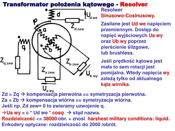
Transformator położenia kątowego - Resolver Resolwer Sinusowo-Cosinusowy. Zasilane jest Ud we napięciem przemiennym. Dostęp do napięć wyjściowych Ua wy oraz Ub wy poprzez pierścienie ślizgowe, lub brushless. Jeśli prędkość kątowa jest mała to sem rotacji jest pomijalna. Wtedy napięcia wy zależą tylko od aktualnego kąta wirnika. • Zd = Zq kompensacja pierwotna == symetryzacja pierwotna. • Za = Zb kompensacja wtórna == symetryzacja wtórna. • Jeśli np. Zd zew= 0 to zwieramy uzwojenie q. • Ua wy = c * Ud we * cosj stąd nazwa. Rozdzielczość <= 38000/obr. + znosi harshest military conditions: liquid. Enkodery optyczne: rozdzielczość do 2000 /obrót.
Brushless resolvers: Z= 220+j206 Vin= 7.5V, 4000Hz Ini= 16mA Pin= 87mW Vout= 4V Rst= 16ohms Rrot= 40ohms accuracy= +-7 minutes (2 speed= 2 cycles per turn): +-2minutes RESOLVER = resolver transducer = encoder = rotary position sensor = motion feedback sensor = transducer sensor = synchro (on occasion) typically: Encoder= resolver + on-board electronics Application in stamping press: feeds rotary position to PLC, Programmable Logic Controller.
A resolver control transmitter has one primary winding, the Reference Winding, and two secondary windings, the SIN and COS Windings.
Ratio of the SIN and COS voltages is consideredchanges in resolvers’ characteristics, such as those caused by aging or a change in temperature, are ignored.
RESOLVER CONTROL TRANSFORMER Has 2 input statorwindings, the SIN and COS windings, and 1 rotoroutput winding. Faza napięcia wyjściowego zależy od kąta wirnika. Both control transmitters and control transformers areunidirectional devices i.e. control transmittersmanufacturers specifications are only valid when theelectrical input is the rotor, and control transformersspecifications are only valid when the electrical inputs arethe stator. Although both can be used "backwards", performance cannot be guaranteed.
Transformator położenia kątowego - mikrosyn Amplituda Napięcia Wyjściowego Może być stosowany przy niewielkich kątach obrotu +- 10o. Jeśli kąt wirnika= 0 to strumień od prądu we w biegunach pionowych i poziomych jest jednakowy. Sem wy w uzwojeniach pionowych i poziomych się znoszą. Po przekręceniu wirnika w lewo, strumień w biegunach pionowych jest większy niż w poziomych Sem w uzwojeniach wy pionowych są większe niż w poziomych. Powstaje wypadkowa sem wy, proporcjonalna do kąta wirnika.
Absolute rotary encoder • Kontakty nigdy • nie przełączają • idealnie • jednocześnie • problem Gray encoding A metal sheet is affixed to an insulating disc. Stationarysliding contactswipe against the metal sheet. As the disc rotates, some of the contacts touch metal, while others fall in the gaps where the metal has been cut out. The metal sheet is connected to a current source, and each contact is connected to a separate electrical sensor. Each possible position of the axlecreates a unique binary code in which only some of the contacts areconnected to the current source.
Gray encoding 4-bit Gray code 0000 0001 0011 0010 0110 0111 0101 0100 1100 1101 1111 1110 1010 1011 1001 1000 3-bit Gray code 000 001 011 010 110 111 101 100 Zawsze zmienia się tylko jeden bit z informacją o położeniu wirnika. Sąsiednie kody odpowiadają sąsiednim położeniom wirnika.
Incremental encoder – najpopularniejsze, tanie i dobre Relative rotary encoder == incremental encoder, is used when absolute encoding methods would be too cumbersome, because of the size of the patterned disc. This method also uses a disc attached to the shaft, but this is a much smaller disc marked with a large number of radial lines like the spokes of a wheel. An optical switch, such as a photodiode, generates an electrical pulsewhenever one of the lines passes through its field of view. An electronic control circuit counts the pulses to determine the angle through which the shaft has turned. To identify the direction of rotation the single optical sensor must be upgraded to two sensors placed at slightly different angles around the shaft. The direction of rotation can be inferred from the order in which the two sensors detect each radial line. This type of encoder is known as a quadrature encoder. Myszy komputerowe miały enkodery inkrementalne. Obecnie zostały wyparte przez myszy optyczne.
Miniature Absolute magnetic shaft encoder Non-contacting magneticsingle chip sensing technology. Rotary absolute shaft encoder. Analog (in 10-bit resolution) or a pulse width modulated PWM digital output. PWM output provides a pulse width duty cycle that is proportional to the absolute shaft position. PWM output is available in 10-bit or12-bit resolutions. Shaft Speed, Shaft torque: Sleeve Bushing:100 RPM max, 0.5 ±0.2 in. oz.Ball Bearing:15,000 RPM max, 0.05 in. oz.
Napięcie wyjściowe analogowe. 10-bit PWM:Position= ((ton × 1025)/ (ton +toff))–1 Napięcie wyjściowe PWM.