Download
1 / 20
220 likes | 523 Views
High Temperature Superconductors for the ITER Magnet System and Beyond. W.H. Fietz , S. Fink, R. Heller, P. Komarek, V.L. Tanna, G. Zahn Forschungszentrum Karlsruhe, Institut für Technische Physik, Karlsruhe, Germany G. Pasztor, R. Wesche

E N D
High Temperature Superconductors for the ITER Magnet System and Beyond W.H. Fietz, S. Fink, R. Heller, P. Komarek, V.L. Tanna, G. Zahn Forschungszentrum Karlsruhe, Institut für Technische Physik, Karlsruhe, Germany G. Pasztor, R. Wesche Centre de Recherches en Physique des Plasmas, Villigen, Switzerland E. Salpietro, A. Vostner European Fusion Development Agreement, Close Support Unit, Garching, Germany • Motivation • HTS Basics • Fusion relevant application of HTS superconductor BiSCCO • Prospects and Challenge for YBCO superconductor
Long Term Fusion Magnet R&D ITER Demo / Proto Commercial Fusion Power Plant ≈2012 ≈2030 ≈2045 • Use of High-Tc Superconductors allows • higher operating temperatures of 20 K to 77 K save investment higher efficiency • much lower effort for thermal shielding save investment Need for Efficiency
Efficiency optimization For commercial power plants it is essential to reduce power consumption ITP - refrigerator: 2 kW@ 4.4 K = 0.7 MW electric power ITER: 64 kW@ 4.4 K = 22 MW electric power DEMO or Proto: ??? With a magnet system at 20 K a fusion machine would be much more efficient by a factor of 5-10 on electric power consumption for cryogenics. Great would be a machine with a superconducting magnet system at 65 K to 77 K! Cooling with liquid nitrogen would be possible!
Pressure HgBaCaCuO TlBaCaCuO BiSrCaCuO YBaCuO BiSCCOYBCO LaSrCuO LaBaCuO in 2001:MgB2 (39K) Tc of Superconductors
Use of High-Tc Superconductors (HTS)allows higher operating temperatures YBCO is most promising YBCO @ 20 K BISCCO @ 20 KYBCO @ 65 K but Carnot makes sure:even 20 K would ensure much higher efficiency
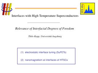
CuO2-Layers (s.c.) Spacing Layer CuO2 -Layers (s.c.) Charge Reservoir / Doping Problems of High-Tc Materials • Layered structures • Correct orientation necessary! • S.C. properties depend on doping • Grain boundaries are detrimental • Brittle materials (ceramics) • Long time R&D was necessary on the road to High-Tc cables For example: 90 K Superconductor YBa2Cu3O7
c-axis c-axis c - axis BiSCCO is available for technical use Long length of BiSCCO superconductor are available on the market from several companies. For example: 1200m BiSCCO tape from European Advanced Superconductor, Hanau, Germany c-axis orientation necessary for BiSCCO - > rolled tapes
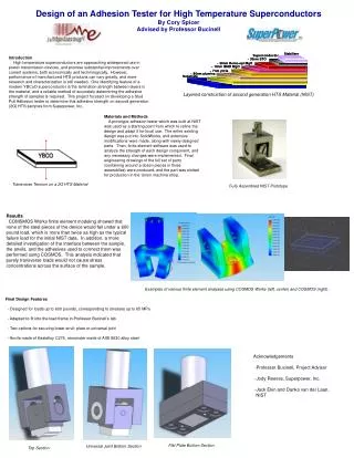
Solution: Current lead consisting of three parts: • Connection to low Tc S.C. HTS module (Bi-2223/AgAu) Copper heat exchanger • 4.5 K 4.5 K - 65 K 65 K - 300 K HTS current lead for ITER (BiSCCO) • In the frame of the EU Fusion Development Program, a 70 kA HTS current lead with Bi - 2223/AgAu superconductor was developed and tested in FZK. • The ITER requirements: • Safety: Withstand a loss of He mass flow for 3 min at nominal current (ITER TF-coil @ 68kA). • Space: Horizontal installation in coil - terminal - boxes.
HTS module was fabricated by American Superconductor (AMSC) • HTS tapes are sintered to stacks • Stacks are soldered on SS panels • 12 panels are arranged to form the HTS module Stacks Stainless Steel
70 kA HTS Current Lead Test Arrangement in TOSKA 70 kA HTS current lead B300 Vacuum vessel 80 kA conventional current lead Bus bar III (for connection and in addition for current distribution measurements)
Results from BiSCCO HTS current lead Details: Poster P2T - E - 284 • Stable operation up to 80 kA World record for HTS !! • Temperature profiles agree with calculations • Contact resistances in HTS module okay but for Cu-Cu screw contact too high • Current sharing temperature 77 K at 68 kA (10 mV criterion) • Refrigerator power consumption reduced by a factor of 5 compared to conventional lead • He mass flow stopped at a current of 68 kA ! • The current lead carried the 68 kA without cooling for more than 6 (!) minutes • until a quench occurred HTS current lead is very robust. HTS material can be fabricated in industry with high and reproducible quality. Quench performance of HTS module excellent. HTS current leads can be used in ITER
c - axis c-axis c-axis c-axis c-axis Option YBCO? BISCCO @ 20K is ok but YBCO @ 20 K BISCCO @ 20 KYBCO @ 65 K what's about YBCO? Same problems as BiSCCO plus 3D orientation necessary! But 65 K would be possible!
RABiTS (Rolling Assisted Biaxially Textured Substrates) • Textured substrates are used for the growth of ideal oriented YBCO films. • Under ideal rolling and tempering conditions the {001} - plane is parallel to the rolling plane and the <100> - direction points to the rolling direction. Thus we have a textured substrate • A buffer layer avoids chemical YBCO / tape reaction • The YBCO layer adopts the orientation of the tape • On top a protection layer is placed This is the "Coated Conductor" Methods to grow oriented layers of YBCO • Ion Beam Assisted Deposition + Pulsed Laser Deposition • These vacuum methods work well but growth rate is too low for large scale application
Status of the Coated Conductor • Basic idea realized in 1996 for short length samples - anyhow major difficulties exist: • Homogeneity of long substrates • Buffer layer problem (complicated and time consuming) • Slow growth of YBCO film by sputtering or evaporation Current Status: 10 - 50 m high current coated conductor ( 1 - 2 · 106 A/cm2 @ 77 K, self field) Demonstration of 500 m coated conductor (vacuum methods) aimed for 2006 (Nexans) / 2007 (Japan) / 2008 (USA)
Already achieved in FZK: Chemically depositedbuffer on Ni RABiTs tape and YBCO on SrTiO3 New Virtual HGF Institute for chemical deposition of YBCO (FZK and Universities of Braunschweig, Tübingen, Dresden & Wuppertal G. Kotzyba R. NastB. ObstS. Schlachter W. GoldackerFZK/ITP Open challenges (1): Focus at present on cube textured Ni - alloy substrate tape Challenge: Alternative tapes for fusion application Focus at present on buffer layers / CeO2 on Ni Challenge: New conductive buffer - or no buffer at all ? (increasing stabilization) Best results with slow deposition techniques Challenge:Speed up! - > chemical deposition Industries active in chemical route: - Nexans - Trithor (starting) - American Superconductor
Open challenges (2): 1) From basic physics to technical solutions - Adopt HTS R&D to fusion needs (e.g. Ni substrates are not ideal for fusion) - Development of bundling and cabling techniques (ac loss optimization)
Classic concepts Nb3Sn strand (=0.81mm) (Europa Metalli - LMI) ac - loss optimizedTFMC conductor :Multi stage twisted cable in conduit with central cooling channel, Rated current: 70 kA @ 11.8 T and 4.6 K Development of bundling and cabling techniques ac - loss optimization is one of the most crucial points!
Open challenges (2): 1) From basic physics to technical solutions - Adopt HTS R&D to fusion needs (e.g. Ni substrates are not ideal for fusion) - Development of bundling and cabling techniques - Strand and subcable tests - Fusion conductor development in collaboration with industry 2) Design, Manufacturing and Test of a HTS-Model-Solenoid 3) Design Manufacturing and Test of a TF HTS-Demonstration Coil in Collaboration with Industry
Conclusion: The development, construction and demonstration of a High Temperature Superconductor coil system for Fusionis a scientific and technologic long term challengewhich has to be tackled already now for becoming ready in time. This work should be done in close collaboration of European associations and industry. The benefit from a HTS coil system will help Fusion - to be a commercial success - to secure worlds power generation during the next decades - to generate spin - offs (e.g. power engineering).