Download
1 / 16
160 likes | 283 Views
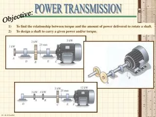
POWER TRANSMISSION Overview of the systems used to transfer power from actuators to the outputs . REVIEW OF ELEMENTARY MECHANICAL CONCEPTS. FOR OUR ANALYSIS & MODELING PURPOSES WE DEAL OF RIGID BODIES. If all points move in lines parallel to one another, we term the motion TRANSLATIONAL

E N D
POWER TRANSMISSIONOverview of the systems used to transfer power from actuators to the outputs
REVIEW OF ELEMENTARY MECHANICAL CONCEPTS FOR OUR ANALYSIS & MODELING PURPOSES WE DEAL OF RIGID BODIES If all points move in lines parallel to one another, we term the motion TRANSLATIONAL In the case of robotic manipulators, certain joints – called linear or prismatic - may be constrained to move along a straight line Elements associated with linear motion are MASSES, SPRINGS and FRICTION
MASS The governing equation of motion developed by Newton is given by F(t) = M x¨ (t) Algebraic sum of the forces acting on a body of mass M is equal to the mass times the acceleration experienced by the body (Newton’s law) Σ Fi(t) = M x¨ (t) It is important to distinguish between mass (M) and weight (W) : M= W/g indicates that weight is a measure of the gravitational force acting on a mass (g gravitational constant = 9.8 m/s2)
SPRINGS A linear spring is a mechanical element that store potential energy: its displacement from its equilibrium position is proportional to the force applied to it The displacement of the spring is given by (Hooke’s law) F(t) - Fp= K x (t) K is the spring constant in units of force/ displacement Fp preload tension that is a force required to keep the spring stretched a prescribed distance In practice, springs are not linear as defined above but, in case of small deformations, the linear approximation is valid
FRICTION • Translational systems also exhibit friction, a force that opposes motion. • Friction is usually nonlinear and dependent on such factors as velocity, pressure between the two moving surfaces and surface composition. • Friction can be broken down into three distinct components: • Viscous friction • Static friction • Coulomb friction • Viscous friction is a retarding force that exhibits a linear relationship between the applied force and velocity: a phyisical component that produces this relationship is the dashpot • F(t) = B x· (t)
STATIC friction – sometimes called starting friction – prevents initial motion. Once motion begins, this force “vanishes” and is represented by the equation: F(t) = ± Fs|(x· =0) The sign will depend on the direction of motion and be such as to oppose the motion; Fs is the magnitude of the static friction force COULOMB friction – also called running friction – has a constant amplitude; its sign is dependent on the direction of velocity. The equation used to represent the running friction is F(t) = Fc sgn (x·) Fc is the magnitude of the Coulomb friction and sgn is the signum function
Phisical systems usually exhibit a combination of all three types of friction therefore it is necessary to provide force sufficient to overcome all the frictional components as well as that required to produce the required acceleration; during deceleration, the frictional components will help to stop the system. This concept is very important for MOTOR SELECTION Components to reduce friction between surfaces are BEARINGS. Bearings come in both linear (for translational motion) and rotary (for rotary motion) configurations: it’s important to realize that to implement mechanical systems, one must ensure that shafts which rotate are properly supported or masses that move across a surface are both constrained to a single degree of freedom and have the minimum friction acceptable Bearings provide this constraints while minimizing the friction between the moving member and the surface to which is movement is referenced
ROTATIONAL motion takes place about a fixed axis: if all the points along some line remain fixed during a motion (case of the rigid body), the body is rotating about that line Dynamical relationships and physical quantities associated with this type of motion are directly analogous to those of translational motion Linear displacements become angular rotations and are typically measured in radians Mass become moment of inertia, its rotational analog that quantifies the property of an element that stores the kinetic energy of rotational motion (higly dependent on geometric properties) Torque is analogous to force in a translational system and is the motive action for rotation
The equation describing the dynamics of a torque inertia system is T(t) = J θ¨(t) = J α(t) where T(t) is the instantaneous torque, θ¨(t) the angular acceleration, J the body’s moment of inertia through the axis of rotaion Torque springs provide a displacement proportional to the applied torque T(t) = K θ(t) Rotational systems also experience frition similar to translational systems so, respectively, we have viscous, static and Coulomb friction in rotay systems expressed by T(t) = B θ·(t) viscous T(t) = ± Ts|(θ·=0) static T(t) = Tc sgn(θ·) coulomb
MOMENT OF INERTIA The computation of the moment of inertia is extremely important in the sizing of motors and in modeling the dynamics of a physical system. The moment of inertia of a body is highly dependent on its shape and, unlike mass, is not a unique property of the body but depends on the axis about which it is computed For a system consisting of “n” discrete point masses: J = Σ Mr²
For the case of bodies of complex geometric shape: J = integral on volume (ρr²dV) Moment of inertia of a body about an axis which is parallel to the one passing through the center of gravity (parallel axis theorem) : J =Jc +Mr²
Example Moment of inertia of a slender bar about an axis at one of its ends y’ Centroidal axis moment of inertia J= 1/12 Ml² The center of mass is located in the middle of the bar at l/2 therefore we obtain Jy’ = 1/12 Ml² + M(l/2)² = 1/3 Ml²
A common error used in computing the moment of inertia about an axis occurs when we approximate the body as a point mass physically located at its center of gravity and then use this point to define the distance of the body from its axis of rotation. In the case shown above, if we had used the center gravity to compute the moment of inertia about the y’ axis, the result would be (point mass M at l/2 from the y’ axis) Jy’ = 1/4 Ml² Comparing the two expressions an error of 25% has been made i.e. a payload of a robot may be incorrectly calculated causing the system unable to perform properly Point-mass approximation should not be used arbitrarily to compute the inertia of an object: in some case this approx is sufficient but a more conservative and better approach is to decompose the body into elementary shapes as shown in a table of centroidal moments and then use the parallel axis theorem to compute the inertia of the object
MECHANICAL WORK & POWER Work may be defined in terms of a force F acting on a body in such a way that the force has a component along the line of motion of its point of application: work is positive if the force acts in the direction of motion and an applied force that is perpendicular to the direction of motion does not work. The equation defining work is: Fs is the component of the force along the path and is dependent on its location in space (is function of s) For a constant force in same direction as displacement: W = F·s It can be shown that if a force is imparted to a body of mass M, causing it to accelerate, the work of this force equals the change in the kinetic energy of the body i.e. W = ½ M(V2)² - ½ M(V1)² V1 initial and V2 final velocity of the body If the effect of gravity is included, the work due to all forces acting on the body is W = [½ M(V2)² + Mgh2] - [½ M(V1)² + Mgh1] The expression in parentheses is the value of total mechanical energy
MECHANICAL WORK & POWER If the body is attached to a linear spring and has no change in potential energy due to gravity, the work done by the resultant forces is W = [½ M(V2)² + ½ K(x2)²] - [½ M(V1)² + ½ K(x1)²] the expression 1/2Kx² being a potential energy as well POWER is defined as the time rato of doing work: P=dW/dt For a force acting in the same direction as the velocity of a body, the average power is: <P> = F<V> (being the <terms> an average value) While P(t) = FV(t) is the instantaneous power For the case of fricional element, the power is dissipated as heat Assuming a constant velocity acting on a dashpot, the average power dissipated a heat is P dissipated = BV²
MECHANICAL WORK & POWER For the case of rotational motion, there are energy relationships that are similar to those of the linear case. Work can be defined in therm of torque T, acting through a given rotational displacement. So: W= Tθ The kinetic energy of a rotational system is given by: Ek = ½ Jω² and similarly, the equation defining potential energy for a torsional spring is: Ek = ½ Kθ² Power for rotational system is then: P(t) = T(t)ω(t)