Download
1 / 36
360 likes | 497 Views
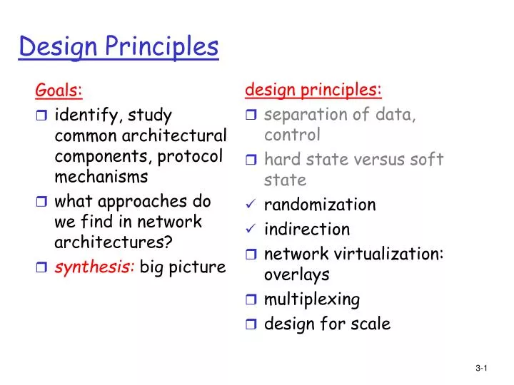
Goals: identify, study common architectural components, protocol mechanisms what approaches do we find in network architectures? synthesis: big picture. design principles: separation of data, control hard state versus soft state randomization indirection network virtualization: overlays

E N D
Goals: identify, study common architectural components, protocol mechanisms what approaches do we find in network architectures? synthesis: big picture design principles: separation of data, control hard state versus soft state randomization indirection network virtualization: overlays multiplexing design for scale Design Principles
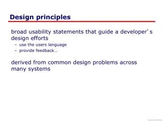
Virtualization of networks Virtualization of resources: powerful abstraction in systems engineering: • computing examples: virtual memory, virtual devices • virtual machines: e.g., java • IBM VM os from 1960’s/70’s • layering of abstractions: don’t sweat the details of the lower layer, only deal with lower layers abstractly
Examples • Connecting local heterogeneous networks • IP over ATM • Resilient overlay networks • VPN
The Internet: virturalizing local networks 1974: multiple unconnected networks • ARPAnet • data-over-cable networks • packet satellite network (Aloha) • packet radio network .. differing in: • addressing conventions • packet formats • error recovery • routing
Cerf & Kahn: Interconnecting two networks • “…interconnection must preserve intact the internal operation of each network.” • “ ..the interface between networks must play a central role in the development of any network interconnection strategy. We give a special name to this interface that performs these functions and call it a GATEWAY.” • “.. prefer that the interface be as simple and reliable as possible, and deal primarily with passing data between networks that use different packet-switching strategies • “…address formats is a problem between networks because the local network addresses of TCP's may vary substantially in format and size. A uniform internetwork TCP address space, understood by each GATEWAY and TCP, is essential to routing and delivery of internetwork packets.” satellite net ARPAnet
Internetwork layer: • addressing: internetwork appears as a single, uniform entity, despite underlying local network heterogeneity • network of networks Cerf & Kahn: Interconnecting two networks Gateway: • “embed internetwork packets in local packet format or extract them” • route (at internetwork level) to next gateway gateway satellite net ARPAnet
source address local header dest. address flag field byte count text checksum seq. # TCP identifier network 8 16 Historical Aside: Proposed Internetwork packet in 1974:
Cerf & Kahn’s Internetwork Architecture What is virtualized? • two layers of addressing: internetwork and local network • new layer makes everything homogeneous at internetwork layer • underlying local network technology (cable, satellite, 56K modem) is “invisible” at internetwork layer
IP-Over-ATM IP over ATM • replace “network” (e.g., LAN segment) with ATM network • ATM addresses, IP addresses Classic IP only • 3 “networks” (e.g., LAN segments) • MAC (802.3) and IP addresses ATM network Ethernet LANs Ethernet LANs
app transport IP AAL ATM phy app transport IP Eth phy ATM phy ATM phy IP AAL ATM phy Eth phy IP-Over-ATM
IP View of the world IP network ATM network
Classical IP-over ATM [RFC 1577] LIS: logical IP subnet • end systems in same LIS have same IP network addr • LIS looks like a LAN • ATM net divided into multiple LIS • Intra-LIS communication via direct ATM connections • How to go from IP addr to ATM addr: ATMARP resolves IP addr to ATM addr (similar to ARP) C D B E A LIS2 LIS1 LIS3 R2 R1
Classical IP-over ATM [RFC 1577] Inter-LIS communication: • source, dest. in different LIS • each LIS looks like a LAN • hop-by hop forwarding: • A-R1-R2-E C D B E A LIS2 LIS1 LIS3 R2 R1
C D B E A LIS2 LIS1 LIS3 NHRP server, S1 NHRP server, S3 NHRP server, S2 NHRP (next hop resolution protocol) [RFC 2332] • source/dest. not in same LIS: ATMARP can not provide ATM dest. address • NHRP: resolve IP-to-ATM address of remote dest. • client queries local NHRP server • NHRP server routes NHRP request to next NHRP server • destination NHRP returns dest ATM address back through NHRP server chain (like routed DNS) • source can send directly to dest. using provided ATM address “ARP over multiple hops”
IP-over-ATM: why? • because it’s there- use ATM network as a link-layer to connect IP routers • can manage traffic more carefully in ATM network (e.g., rate-limit source/dest pairs, provide CBR service) • leave IP untouched – leverage the fact that many users have IP addresses already
Resilient Overlay Networks Overlay network: • applications, running at various sites as “nodes” on an application-level network • create “logical” links (e.g., TCP or UDP connections) pairwise between each other • each logical link: multiple physical links, routing defined by native Internet routing
Overlay network Focus at the application level
Internet Routing • BGP defines routes between stub networks Internet 2 Berkeley.net UMass.net C&W Mediaone UCLA Noho.net
Internet Routing • BGP defines routes between stub networks Internet 2 Berkeley.net UMass.net C&W Mediaone Noho-to-UMass UCLA Noho.net
Internet Routing • BGP defines routes between stub networks Internet 2 Berkeley.net UMass.net C&W Mediaone Noho-to-Berkeley UCLA Noho.net
Internet Routing Congestion or failure: Noho to Berkely BGP-determined route may not change (or will change slowly) Internet 2 Berkeley.net UMass.net C&W Mediaone Noho-to-Berkeley UCLA Noho.net
Internet Routing Noho to UMass to Berkeley • route not visible or available via BGP! • MediaOne can’t route to Berkeley via Internet2 Congestion or failure: Noho to Berkely BGP-determined route may not change (or will change slowly) Internet 2 Berkeley.net UMass.net C&W Mediaone Noho-to-Berkeley UCLA Noho.net
RON: Resilient Overlay Networks Premise:by building application overlay network, can increase performance, reliability of routing Layer 7 routing! Two-hop (application-level) noho-to-Berkeley route application-layer router Virtualize the Internet!
RON Experiments • measure loss, latency, and throughput with and without RON • 13 hosts in the US and Europe • 3 days of measurements from data collected in March 2001 • 30-minute average loss rates • A 30 minute outage is very serious! • Note: Experiments done with “No-Internet2-for-commercial-use” policy
Loss Rate RON Better No Change RON Worse 10% 479 57 47 20% 127 4 15 30% 32 0 0 50% 20 0 0 80% 14 0 0 100% 10 0 0 An order-of-magnitude fewer failures 30-minute average loss rates 6,825 “path hours” represented here 12 “path hours” of essentially complete outage 76 “path hours” of TCP outage RON routed around all of these! One indirection hop provides almost all the benefit!
RON Research Issues • how to design overlay networks? • Measurement and self-configuration • Fast fail-over • Sophisticated metrics • application-sensitive (e.g., delay versus throughput) path selection • effect of RON on underlying network • If everyone does RON, are we better off? • Interacting levels of control (network- and application-layer routing
Virtual Private Networks (VPN) VPNs • SP infrastructure: • backbone • provider edge devices • Customer: • customer edge devices (communicating over shared backbone) Networks perceived as being private networks by customers using them, but built over shared infrastructure owned by service provider (SP)
VPN reference architecture customer edge device provider edge device
VPN: logical view virtual private network customer edge device provider edge device
Leased-line VPN customer site connects to provider edge customer sites interconnected via static virtual channels (e.g., ATM VCs), leased lines
Customer premise VPN • All VPN functions implemented by customer • customer sites interconnected via tunnels • tunnels encrypted typically • SP treats VPN packets like all other packets
Drawbacks • Leased-line VPN: configuration costs, maintainence by SP: long time, much manpower • CPE-based VPN: expertise by customer to acquire, configure, manage VPN Network-based VPN • customer’s routers connect to SP routers • SP routers maintain separate (independent) IP contexts for each VPN • sites can use private addressing • traffic from one vpn can not be injected into another
Network-based Layer 3 VPNs multiple virtual routers in single provider edge device
VPNs: why? • privacy • security • works well with mobility (looks like you are always at home) • cost: many forms of newer VPNs are cheaper than leased line VPNs • ability to share at lower layers even though logically separate means lower cost • exploit multiple paths, redundancy, fault-recovery in lower layers • Need isolation mechanisms to ensure resources shared appropriately • abstraction and manageability: all machines with addresses that are “in” are trusted no matter where they are