Download
1 / 30
300 likes | 437 Views
Backhaul 101. Introduction to the proposed regulated backhaul services. December 3 rd 2007. Content. What is Backhaul? Generic Concepts Access Seeker’s Nearest Available Point of Interconnection (NAPOI) Isolated NAPOIs and Virtual Designated Point of interconnection (VDPOIs)

E N D
Backhaul 101 Introduction to the proposed regulated backhaul services December 3rd 2007
Content • What is Backhaul? • Generic Concepts • Access Seeker’s Nearest Available Point of Interconnection (NAPOI) • Isolated NAPOIs and Virtual Designated Point of interconnection (VDPOIs) • Elected Points of Interconnection (EPOIs) • Regulated UCLL backhaul • Regulated UBA backhaul • The role of commercial backhaul • Glossary • Questions • Appendix A: Information on UBS/Basic UBA • Appendix B: Aggregation
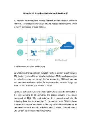
What is Backhaul? • A formal definition of "backhaul" is: "the process of transmitting information to a central point from which it can be distributed over a network". • Backhaul services usually carry traffic on a "point-to-point" basis, without making complex switching decisions about where to send the traffic. • Backhaul allows Access Seekers to connect customers in places where they do not own their own networks.
What is Backhaul? • The backhaul service connects an exchange-based tail or service to another handover point. • A handover point is the boundary between one service and another, or between a service and a Handover Link. • A Handover Link is a cable that connects the Handover Point to the Service Provider equipment (which may be co-located or at a different site) • Regulated backhaul will be ethernet only. Slide 4
Why is it necessary? • To understand the role of backhaul, consider a phone call. It starts at one telephone, travels to an exchange, travels on a trunk to another exchange, and ends at another telephone. Since it's expensive to run millions of wires between telephone exchanges, the telecommunications industry has developed a host of technologies which allow one transmission system to carry many calls (known as trunking). The telephone exchange becomes a collection point, which aggregates tens, hundreds, or thousands of calls onto a single transmission link between exchanges.The same need exists for data networks like the Internet. Customer traffic is aggregated close to the users, so that the transmission system can carry a large number of requests on a small number of links.If an Access Seeker doesn't own a trunk network then it needs to find some way of moving around traffic from a large number of customers. An ISP may have all its switches in Auckland, with subscribers all over New Zealand. To connect a customer in Greymouth the ISP needs to pay another telecommunications carrier to collect the customer traffic in Greymouth, carry it to Auckland, and deliver it to the ISP's data centre. This is an example of a backhaul service. Slide 5
What is bandwidth? • In telecommunications, "bandwidth" measures how much information a network can carry. And because most modern telecommunications services are based on digital networks, digital measures of bandwidth have become the most common and most familiar way to express the capacity of all kinds of network links.Bandwidth is expressed in multiples of bits per second. A standard telephone is allocated 64 Kbps (kilobits, or thousands of bits) per second of communications bandwidth. Backhaul networks, which carry the traffic of huge numbers of customers, are measured in millions of bits per second (megabits per second, or Mbps), up to billions of bits per second (gigabits per second, or Gbps). Slide 6
Generic concepts - NAPOI Access Seeker’s Nearest Available Point of Interconnection. • The NAPOI are defined as 29 geographic points around New Zealand that have been chosen to optimise network efficiency. Currently 16 of these sites are operational and 13 additional sites are still awaiting EAS deployment. • 16 have already been deployed: Auckland Central, Glenfield, Henderson, Mt Albert, Torbay, Remuera, Papakura, Papatoetoe, Hamilton, Wellington, Naenae, Porirua, Christchurch, Riccarton, Dunedin, Howick • 13 are to be built: Cromwell, Greymouth, Invercargill, Kerikeri, Levin, Napier, Nelson, New Plymouth ,Palmerston North, Rotorua, Tauranga, Timaru, Whangarei • These points were discussed and agreed at the TCF. Slide 7
Generic concepts – iNAPOI and VDPOI • For Access Seekers with UCLL or EUBA in the new NAPOI areas, where no competitive infrastructure exists within 5 kilometres of the relevant NAPOI, eg Kerikeri or Cromwell (known as an isolated NAPOI or iNAPOI), then a virtual designated point of interconnect (VDPOI) will be assigned, if requested. For example, Dunedin may be the VDPOI for the Cromwell NAPOI. • The network investment manager determines the VDPOI for each iNAPOI. The VDPOI is the geographically closest NAPOI to the iNAPOI. The network investment manager will inform product management to manage the transition from iNAPOI to NAPOI. Slide 8
Generic concepts – EPOI (UCLL only) An Access Seeker may also elect to terminate the UCLL Backhaul service at an intermediate point between the First Handover Point and the NAPOI. These points, for the purposes of this document, are defined as an Access Seeker’s elected point of interconnection (EPOI) and their use as an EPOI is subject to the following rules: The EPOI must be one of Telecom’s UBA First Data Switch sites that the UCLL Backhaul Service transits between the First Handover Point and the NAPOI; Once the EPOI is established, the UCLL Backhaul Service from all local telephone exchanges served by that EPOI will terminate at that point instead of the NAPOI; and The UCLL Backhaul Service is not available from the EPOI to any NAPOI An example would be in Queenstown where the Access Seeker may have presence in that location despite it not being a NAPOI Slide 9
Regulated UCLL Backhaul • UCLL/Co-location allow Access Seekers to install their own access equipment which connects to Telecom’s copper loop. • This equipment can be in the Telecom Exchange (co-located) or external. • The equipment connects to the handover point using a Handover Link. • Regulated backhaul will connect the site to the NAPOI (or VDPOI/EPOI).The Access Seeker can aggregate their own UCLL traffic onto a single regulated backhaul. • Commercially they will be able to aggregate non-UCLL traffic. Slide 10
Demarcation: Regulated UCLL Backhaul • The Access Seeker installs their DSLAM in the local exchange. • They connect to the UCLL Handover Point using a Handover Link. • Regulated backhaul goes from a relevant frame in an exchange to the relevant frame at the NAPOI (or VDPOI/EPOI) • NAPOIs are defined as 29 Tier 0,1 and 2 sites. • The Access Seeker must either: • (a) handover at the UCLL HoP; • (b) handover at the NAPOI, VDPOI, or EPOI; or • (c) use commercial backhaul to take them to another agreed POI. Slide 11
Regulated EUBA backhaul • EUBA services on an EAS can be aggregated across a common backhaul infrastructure to the NAPOI (or VDPOI). • Each Access Seeker would specify how much bandwidth they required. • The Access Seeker can effectively specify a contention ratio. • The traffic priority tagging will specify how traffic is managed. • It is the responsibility of the Access Seeker to ensure applications are managed end to end to ensure this capacity is not ‘flooded’. • EUBA traffic from several EAS can be aggregated at the NAPOI on to a single Handover Link, subject to bandwidth. Note that this aggregation could also be contended. Slide 12
Demarcation: Regulated EUBA Backhaul • The Enhanced UBA tail includes both the ADSL2+ line and the connectivity between the DSLAM and the Ethernet Aggregation Switch. • Regulated backhaul goes from the trunk side of the EAS to the NAPOI etc. • NAPOIs are defined as 29 Tier 0,1 and 2 sites. • The Access Seeker must either: • (a) handover at the EAS HoP; • (b) handover at the NAPOI or VDPOI; or • (c) use commercial backhaul to take them to another agreed POI. Slide 13
Handover Links and connections • The Handover Link connects Access Seeker equipment to the physical Handover Point, or OFDF at the NAPOI etc. • The handover connection is used to connect the trunk side of the EAS to the Handover Point and is only required for EUBA tails • A Handover Link is required to connect the Access Seeker equipment to the backhaul service, irrespective of whether that is commercial or regulated backhaul. • UCLL will have a handover link in the ‘unbundled’ exchange as well as the NAPOI Slide 14
Commercial Backhaul • Why is it important? Commercial backhaul will link the 29 NAPOI with one another allowing Access Seekers to transport across metro areas and nationally. • What is the market need? There are a different options available dependant on the Access Seeker’s requirements. Some Access Seekers will need national point to point links and other will want multi-product (regulated and commercial products), multipoint backhaul services. • Who will provide commercial services? There is currently a number of different providers offering a range of commercial backhaul service. Slide 15
Additional Questions • Telecom infers that each local exchange (for UCLL Backhaul) or first data switch (FDS) (for UBA Backhaul) is assigned to a particular NAPOI. Can Telecom please provide a list of which local exchange or FDS it proposes should be assigned to each NAPOI. Link: • Telecom interprets the NAPOI as being that which is nearest to the End User. Will this potentially require the Access Seeker to either extend their network to each NAPOI nominated by Telecom or purchase backhaul commercially? Could this also require the Access Seeker to interconnect with multiple NAPOIs in the same centre (i.e. Auckland, Wellington and Christchurch) in order to get backhaul traffic from local exchanges in more than one NAPOI area. Yes. Multiple NAPOIs in the larger cities reflect the structure of Telecom’s NGN. Telecom itself connects at each of these NAPOIs on an equivalence basis so Access Seekers face no competitive disadvantage from this structure. The need for multiple NAPOIs is to provide diversity and load balancing. Eg There is a maximum number of customers supported by each NAPOI. Slide 16
Additional Questions • Telecom has reserved the right to designate new NAPOIs, and perhaps withdraw existing NAPOIs, from time to time. Under what circumstances would this re-designation occur? The NAPOIs align with the Tier 0,1 and 2 nodes in our network architecture. The location of these nodes is driven by the population density i.e. we limit the maximum number of end customers served by a single node, and network transport links design and reliability issues primarily driven by geographic factors e.g. if an area is geographically isolated we may put more equipment in the region for service reliability reasons. Changes will be driven by things like population changes e.g. if the population in a region grows sufficiently we may need to create a new Tier 2 node, and we might conceivably remove a Tier 2 node if sufficient diverse links became available to a geographically isolated area. • For UBA Backhaul, the FDSs and the NAPOIs are co-located (except for the Upper Hutt FDS). As Telecom interprets the NAPOI as being that which is nearest to the End User, would there be any need for UBA Backhaul apart from the Upper Hutt FDS? In the future yes – the number of FDS will expand as the Telecom network is deployed. See link Slide 17
Additional Questions • Why has Telecom chosen NAPOI locations which are different to the existing POIs for UBS, Basic UBA and voice interconnection? Can Telecom please provide a list of the POI locations for UBS, Basic UBA and voice interconnection. The NGN is a fundamentally different and new network compared to the PSTN. Therefore there is no particular reason why PSTN POIs should map to NGN NAPOIs. UBS and BUBA are ATM services, the NAPOIs are Ethernet-related services. So again there is a different network with different nodes. However overtime as Telecom moves from PSTN to VOIP based services and migrates from ATM to Ethernet these points will be consolidated. POI list • Can Telecom please describe the purpose of the NAPOI variants, namely VDPOI, iNAPOI and EPOI. Covered in earlier slides • EPOIs only exist for UCLL Backhaul and must be at one of Telecom's UBA FDSs. However, the FDSs and the NAPOIs are co-located (except for the Upper Hutt FDS), so what purpose do the EPOIs currently serve? None currently but as with question 4 the need will become more apparent has the new network is deployed. Slide 18
Additional Questions • When no Access Seeker or third party has existing network infrastructure capable of offering a backhaul service for the UCLL/UBA Service within 5 kilometres of a particular NAPOI and has no plans to build such infrastructure, then the geographically closest NAPOI will be defined as a VDPOI. Can Telecom please explain how it was determined that 5km was the appropriate distance? The VDPOI definition relates to national backhaul rather than the regulated regional backhaul – this is an important distinction to bear in mind as the competition tests are different. For national backhaul the issue is whether there is a national backbone connection sufficiently close to the NAPOI to enable a reasonable connection so that it is possible to compete in the market for connecting NAPOIs together in relation to each NAPOI. For regulated backhaul the issue is whether there is a fibre network in the area able to be used to provide the exchange to NAPOI (UCLL) or FDS to NAPOI (UBA) connection. The 5 km is an historical number which was used in relation to how far from a POI an interconnect link would be run for the standard charge. Beyond the 5 km an additional charge was made for the extra costs Telecom would be incurring by providing long distance interconnect links. It had seemed that this was a reasonable proxy for extending out from a NAPOI. Slide 19
Additional Questions • Can Telecom please explain how the indicative list of exchange groupings in Appendix 5 of the STPs is intended to be used? This list is to help Access Seekers map exchanges/FDS to NAPOIs. • Why has Telecom proposed two speed options for UCLL Backhaul and four speed options for UBA Backhaul? Why aren’t the four speed options available for both backhaul options? Can Telecom please explain how the speeds were determined? Unlike UBA backhaul, UCLL backhaul does not pass through any aggregation device therefore the speeds can only be constrained by the Network Interface Device (eg media converters) and there is only a limited bandwidth available on these devices. Speed steps were determined through consultation with the TCF which took into consideration the minimum number of customers required for UCLL and EUBA. • Why has Telecom proposed a point to point service for UCLL Backhaul and an aggregated service for UBA Backhaul? EUBA passes through an Ethernet aggregation switch therefore makes EUBA aggregation “possible” . UCLL backhaul doesn't pass through an aggregation switch therefore it cannot easily aggregate the UCLL services, however, Access Seekers can insert their own aggregation devices. Slide 20
Additional Questions • Why has Telecom proposed 20 distance steps for the monthly rental price, when there are five steps (S plus A to D) for the Telecom commercial backhaul product? • The cost of backhaul is a function of distance, geography, capacity and technology. When drafting the STP we were aware that some incumbents overseas have adopted a fixed cost plus a per metre/km cost approach. Whilst this is the closest approximation to underlying cost, the advice we received was that it would have been impractical from a billing perspective. Accordingly, we selected as small a number of distance groupings as possible that would be a fairly accurate proxy of underlying cost but be able to be implemented from a billing perspective. Plus the number of groupings did result in a fair spread across all the potential backhaul permutations. Greater granularity in price will more optimally enable the pricing structure of the service to more accurately reflect the underlying cost structure of this service. As such, the greater the number of price points, the more efficient signals pricing will provide to Access Seekers leading to more optimal allocations of resources. Whilst the Commission has noted that our commercial backhaul product has 5 bands, we do not consider this relevant as the pricing is not cost plus but value maximising. Whilst cost is an important factor when setting pricing under a value maximising construct, there are other factors to consider including capacity, competition and business objectives. This service is more analogous to the UPC service which the Commission benchmarked with 11 cost steps. Slide 21
Additional Questions • Why has Telecom not proposed a price for the 100 Mbps capacity handover connection? It was an error. • Which parties took part in the TCF working party on the backhaul services? • Kenneth Barnett (CallPlus) • Sebastien Pham (ihug/Vodafone) • Craig Young (TelstraClear) • Mike Moran (Telecom) • Chris Dyhrberg (Telecom) • Alan Mitford-Taylor (Telecom) • Jeremy Hall (Telecom) • Steven Bond-Smith (Orcon) • Gary Hooker (Telecom Retail) • Paul Clarkin (WorldxChange) • Tex Edwards (NZ Comms) (occasional attendance) Slide 22
Glossary Slide 23
Glossary Slide 24
Appendix A: UBS/Basic UBA • UBS/Basic UBA is sold as an L2TP tail from the end-user premises to the first ATM Data Switch (USAP) • However the interface specification requires we insert an L2TP Access Concentrator (LAC) into the tail. This is done by routing traffic through a BRAS and into the IP Core. • We then route the L2TP tunnel to the designated USAP or Point of Interconnect. • Regulated Backhaul, which is between the first Data Switch and the NAPOIs, is not needed because the basic tail, with zero backhaul, already is at the USAP/NAPOI. Slide 26
Appendix A: UBS comparing how we sell with what we build • The above diagram shows how we ‘sell’ the service, i.e. Tail + commercial backhaul, versus how we build the service. • Technically the tail includes the LAC, which is delivered on the same BRAS used by Xtra Retail, the IP Core and the ATM Node. • The requirement for a LAC means that the traffic is routed to the actual handover ATM node directly • This could create an anomaly where the designated USAP is actually closer to the LAC than the URSA USAP. However we bill based on where the user is, not where the BRAS is. • Any backhaul dimensioning is solely done over the ATM-ATM POI link • Ethernet Backhaul is currently being trialed. This can be done easily because the interface is L2TP over IP – the IP layer hides the Layer 2 (Ethernet or ATM) technology. Slide 27
Appendix A: UBS/Basic UBA: URSAs and USAP • Unbundled Regional Service Areas The country is divided into geographical areas. All DSLAMs in those areas belong to that URSA (see picture). • Unbundled Service Aggregation Point Each URSA has a USAP which correlates to the first data switch.This is the first point interconnect can occur for UBS Customers.Sometimes the USAP is not in the URSA, for example Northland’s USAP is located at Airedale st Exchange.Mayoral Drive has four USAPs (four different ATM switches) to cover North Auckland, North Shore, Hobsonville and West Auckland URSAs. The ISP either uses four handover links at Mayoral drive or pays commercial backhaul to combine them into one handover link. • Point of Interconnect This is where the service is handed over to the Service Provider. It must be a USAP.Some customers have multiple POIs. • Regulated Backhaul All UBS POIs coincide with NAPOIs and as such no regulated options exist. • Commercial Backhaul Commercial backhaul is the ‘logical’ distance between the first USAP and the actual POI. As the tail ‘ends’ within the IP Core, the physical and logical backhaul constructs are different.
Appendix B: What is Aggregation? • Having one physical backhaul circuit per tail is uneconomic. To make it economic it is necessary to aggregate multiple services onto the same backhaul service. • Aggregation allows multiple services to share a common bandwidth, which is often less than the sum of the services. The ratio of non-aggregated bandwidth to aggregated bandwidth is known as the contention ratio. • Aggregation requires an aggregation function at each end. There are several options • The Service Provider can aggregate their services in their equipment at both ends. • Telecom can aggregate traffic at both ends, or at just one end. • EAS-based services are aggregated by default and therefore it makes sense to deliver as an aggregated service. • UCLL is easier to deliver as point-to-point ethernet, with aggregation as an additional item. Slide 29
Appendix B: Multi-service Aggregation Issues Aggregation Functions Sharing Bandwidth: Aggregation allows us to combine service instances together Contention: Contention allows us to aggregate several services together over a smaller bandwidth than the sum. VLAN mapping: To ensure uniqueness it may be necessary to translate VLAN addresses to new ones.Parameter Mapping: It is possible to map other parameters such as Priority settings, if required. • Aggregating several services means that you require a pipe that can carry all of those services simultaneously. • The services need to be compatible with each other, e.g. not use overlapping VLAN IDs.VLAN IDs are particularly an issue as these need to be unique in the new pipe • Other ethernet characteristics need to be at least compatible and ideally constrained equally. • The backhaul or handover (both points of aggregation) can be smaller than the sum of bandwidths of the inputs, but if so then the behaviour of what happens when the pipe is congested needs to be defined and managed at the point where the contention occurs. Again this could constrain some features. • For EAS-based services the EAS can act as an aggregator, so services could be aggregated on to the single backhaul service. • For UCLL the traffic would need to pass through an aggregator device, which does not currently exist. Slide 30