Download
1 / 37
370 likes | 755 Views
Exposure Factors Modification. By Professor Stelmark. After the lecture student will:. Explain relationship between voltage waveform and radiographic density. List the general principles of the exposure compensation for pediatric patients.

E N D
Exposure Factors Modification By Professor Stelmark
After the lecture student will: • Explain relationship between voltage waveform and radiographic density. • List the general principles of the exposure compensation for pediatric patients. • Utilize exposure compensation techniques for casts and splints imaging. • Discern between patients with different body habitus. • Define Anode Heel Effect. • List destructive and additive pathologies. • Explain applications of different compensating filters.
Appropriate exposure factor selection and its modification for variability in the patient are critical to the production of an optimal quality radiograph.
Effect of Voltage Waveform There are five voltage waveforms: half-wave rectification, full-wave rectification, three-phase/six-pulse, three-phase/twelve-pulse, and high-frequency.
The relationship between x-ray quantity and type of high-voltage generator provides the basis for another rule of thumb used by radiologic technologists. If a radiographic technique calls for 72 kVp on single-phase equipment, then on three-phase equipment, approximately 64 kVp—a 12% reduction—will produce similar results. High-frequency generators produce approximately the equivalent of a 16% increase in kVp, or slightly more than a doubling of mAs over single-phase power.
Pediatric Patients Pediatric chest radiography requires the technologist to choose fast exposure times to stop diaphragm motion in patients who cannot or will not voluntarily suspend their breathing. This fast exposure time may eliminate the possibility of using automatic exposure control (AEC) systems for pediatric chest radiography.
Exposure factors used for the adult skull can be used for pediatric patients 6 years of age and older because the bone density of these children has developed to an adult level. However, exposure factors must be modified for patients younger than 6 years of age. It is recommended that the radiographer decrease the kVp value by at least 15% to compensate for this lack of bone density.
For examinations of all other parts of pediatric patients' anatomy, general rules can be used for determining the proper exposure techniques. Recommendations for pediatric exposure techniques, which have been derived from technique charts established for adult.
Casts and Splints Casts and splints can be produced with materials that attenuate x-rays differently. Selecting appropriate exposure factors can be challenging because of the wide variation of materials used for these devices. The radiographer should pay close attention to both the type of material and how the cast or splint is used.
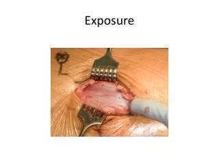
For severe fractures with significant displacement or fragmentation, a surgical procedure is required. The fracture site is exposed, and screws, plates, or rods are installed as needed to maintain alignment of the bony fragments until new bone growth can take place.
In many instances, minor fractures may be reduced in the ER and will need postreduction films once a cast is placed at the fracture site. Any limb with a cast will require an increase in exposure techniques because of the increased thickness of the part and the type of cast used. Plaster casts are thicker, heavier, and denser than fiberglass casts. Therefore, they will require the greatest increase in exposure techniques.
One method of approaching the exposure factor conversion is to consider whether the cast is still wet from application or whether it is dry. This approach states that an increase of 2 times the mAs is needed for dry plaster casts and an increase of 3 times the mAs is needed for wet plaster casts.
Splints Splints present less of a problem in determining appropriate exposure factors than casts. Inflatable (air) and fiberglass splints do not require any increase in exposure. Wood, aluminum, and solid plastic splints may require that exposure factors be increased, but only if they are in the path of the primary beam. For example, if two pieces of wood are bound to the sides of a lower leg, no increase in exposure is necessary for an AP projection because the splint is not in the path of the primary beam and does not interfere with the radiographic image. Using the same example, if a lateral projection is produced, the splint is in the path of the primary beam and interferes with the radiographic imaging of the part. This necessitates an increase in mAs to produce a properly exposed radiograph.
Body Habitus Body habitus refers to the general form or build of the body, including size. It is important for the radiographer to consider body habitus when establishing exposure techniques. There are four types of body habitus: sthenic, hyposthenic, hypersthenic, and asthenic.
Pathology Pathologic conditions that can alter the absorption characteristics of the anatomic part being examined are divided into two categories. Additive diseases are diseases or conditions that increase the absorption characteristics of the part, making the part more difficult to penetrate. Destructive diseases are those diseases or conditions that decrease the absorption characteristics of the part, making the part less difficult to penetrate. Generally speaking, it is necessary to increase kVp when radiographing parts that have been affected by additive diseases and to decrease kVp when radiographing parts that are affected by destructive diseases.
Density and the Anode Heel Effect The intensity of radiation emitted from the cathode end of the x-ray tube is greater than that emitted at the anode end; this phenomenon is known as the anode heel effect. Greater attenuation or absorption of x-rays occurs at theanode end because of the angle of the anode; x-rays emitted from deeper within the anode must travel through more anode material before exiting; thus they are attenuated more.
Studies show that the difference in intensity from the cathode to the anode end of the x-ray field when a 17 inch (43 cm) image receptor (IR) is used at 40 inch (100 cm) SID can vary by as much as 45%, depending on the anode angle. The anode heel effect is more pronounced when a short SID and a large field size are used.
Applying the anode heel effect to clinical practice will assist the technologist in obtaining quality images of body parts that exhibit significant variation in thickness along the longitudinal axis of the x-ray field. The patient should be positioned so that the thicker portion of the part is at the cathode end of the x-ray tube and the thinner part is under the anode (the cathode and anode ends of the x-ray tube usually are marked on the protective housing). The abdomen, thoracic spine, and long bones of the limbs (such as the femur and the tibia/fibula) are examples of structures that vary enough in thickness to warrant correct use of the anode heel effect.
Compensating Filters Body parts of varying anatomic density may result in an image that is partially overexposed or underexposed because the anatomic parts will attenuate the beam differently. This problem can be overcome through the use of compensating filters, which filter out a portion of the primary beam toward the thin or less dense part of the body that is being imaged. Several types of compensating filters are in use; most are made of aluminum; however, some include plastic as well.
Compensating filters in common use include the following: •Wedge filter: Mounts on the collimator; the thicker portion of the wedge is placed toward the least dense part of the anatomy to even out the densities. This filter has numerous applications; some of the most common include AP foot, AP thoracic spine, and axiolateral projection of the hip. •Trough filter: Mounts on the collimator and is used for chest imaging. The thicker peripheral portions of the filter are placed to correspond to the anatomically less dense lungs; the thinner portion of the filter corresponds to the mediastinum. •Boomerang filter: Is placed behind the patient and is used primarily for shoulder and upper thoracic spine radiography, where it provides improved visualization of soft tissues on the superior aspect of the shoulder and upper thoracic spine.
Arrangement of apparatus with the use of an aluminum step-wedge for serial radiography of the abdomen and lower extremities.

![[Radiography] Technique - Exposure Factors](https://cdn0.slideserve.com/546181/radiography-technique-exposure-factors-dt.jpg)