Download
1 / 33
330 likes | 485 Views
Chapter One Viewing an Object . Objectives. Upon completion of this chapter the student will be able to: Define descriptive geometry. Define the following terms: projection planes, projection lines, and line-of-sight.

E N D
Objectives Upon completion of this chapter the student will be able to: • Define descriptive geometry. • Define the following terms: projection planes, projection lines, and line-of-sight. • Describe the two types of orthographic projections and where they are used. • Name the six views produced by a multiview drawing. • Define folding lines. • Explain the importance of folding lines. • Describe how measurements are transferred from view to view. • Construct an orthographic (multiview) projection using manual methods and AutoCAD.
Objectives Upon completion of this chapter the student will be able to: • Define and list the three categories of axonometric projections. • Describe how an isometric scale is constructed. • Construct an isometric projection using manual methods and AutoCAD. • Define and describe the three categories of oblique projections. • Construct an oblique projection using manual methods and AutoCAD. • Define ground plane, station plane, vanishing point, picture plane, ground line, and visual rays. • Define one-point perspective, two-point perspective, and multiview perspective. • Describe and construct a multiview perspective.
Objectives Upon completion of this chapter the student will be able to: • List and describe the three types of three-dimensional models produced using AutoCAD. • Describe the difference between nonparametric and parametric solid models. • Describe the difference between paper space and model space. • Know how to toggle between paper space and model space. • Use mview and vpoint to produce an orthographic and isometric projection. • Use mvsetup to generate orthographic and isometric projections.
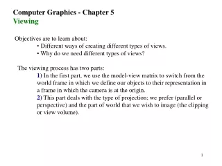
Types of Two Dimensional Views Two Dimensional Views can be divided into four major classes: • Orthographic Projections • Axonometric Projections • Oblique Projections • Perspective Projections
Orthographic Projection Two standards used in the creation of Orthographic Projections: • First Angle Projections • Third Angle Projections
Orthographic Projection Key Words and Phrases Orthographic Projection Multiview Drawing PlaneHorizontal Plane Profile Plane Frontal Plane Projection Plane Line of Sight Object Lines Adjacent View Folding Lines Miter Lines
First Angle Projection Receives it name because the object, is placed in the first quadrant. In a first angle projection, the top view is generated by projecting the object’s contours down onto the horizontal plane. The right side view is generated by projecting the right side of the object through the object to the profile plane. Thus resulting in an arrangement as follows:
Third Angle projection Receives its name from the fact that the object is placed in the third quadrant. In this method the top view is projected up onto the horizontal plane. The right side view is generated by projecting the object’s contours onto the profile plane.
Using AutoCAD to create two-dimensional multiview drawings • Step #1 • Start by using the RECTANG command to draw a 2" square. The coordinates for the location of the square are not important at this time. • Step #2 • Now start transferring measurements to the front view by first drawing a line from the lower left-hand corner of the object to an undetermined point below the object. Then, draw a line from the lower right-hand corner of the object to an undetermined point below the object. Thus establishing the sides of the object in the front view. • Step #3 • The bottom edge of the object is created by moving down several inches below the top view of the part and drawing a line that crosses both lines that were extend downward. • Step #4 • The top edge of the object (in the front view) is created by using the OFFSET command. Finally, the FILLET command with a zero radius can be used to trim off the excess length of the lines revealing a plan and front view of the object.
Using AutoCAD to produce an Isometric Projection Isometric Left Isometric Right Isometric Top
Diametric Projections • In a Diametric Projection only two axis form equal angles, instead of all three like the isometric projection. These angles will be greater than 90° and less than 180°, but not to equal 120°. An angle of 120° is not used because it would produce an isometric projection. The third angle will be less than or greater than the angle chosen for the first two.
Trimetric Projections In a Trimetric Projection none of the three-principle axis form equal angles. The result is a view that contains three different scale factors, making these types of projections difficult to generate. However, an infinite number of possible projections that can be achieved.
Oblique Projection The projection plane is set parallel with the front surface of the object. However, the line of sight will be at an angle to the projection plane producing a view that reveal all three axis’s (length, width and depth)
Using AutoCAD to produce an oblique projection Step #1 Start by drawing the front face of the angle bracket. This is the edge that reveals the thickness of the bracket. Step #2 Next, continue working on the front view, but now concentrate on drawing the face labeled “Back Face”. This includes placing the hole in that face. Step #3 Execute the UCS command to rotate the cross hairs to a 45° angle, to generate the protruding lines and giving the object the illusion of depth. Finally, the face containing the hole, is moved to its proper location at the back of the part. Resetting the ucs in this step it is not necessary when using AutoCAD’s Object SNAP commands. Step #4 Draw a line from the upper left-hand corner of the face showing thickness, to the lower left-hand corner of the face containing the hole. Next, copy the hole from its present position to a position 0.5 inches in front of the current hole. This will give the hole the illusion of depth when finished. Step #5 Complete the projection by adding any missing lines, and remove the excess lines by using the TRIM and ERASE commands.
Perspectives Projections Perspective projections give the object a more natural appearance by allowing the projection lines to converge to a single point. This type of drawing is more readily used in the art world, because this illusion of lines appears more realistic.
Types of Three-Dimensional Views Orthographic Projection Isometric Projection Perspective Projections
Layout Space/Model Space Model Space Layout Space
Orthographic Projection / Isometric Projections Using Mview - Point
Using Mvsetup Command: MVSETUP Initializing... Enable paper space? (No/<Yes>): Y Entering Paper space. Use MVIEW to insert Model space viewports. Regenerating drawing. Creating the default file mvsetup.dfs in the directory C:\AV2\AVWIN\. Align/Create/Scale viewports/Options/Title block/Undo: C Delete objects/Undo/<Create viewports>: C Available Mview viewport layout options: 0: None 1: Single 2: Std. Engineering 3: Array of Viewports
Using Mvsetup Continued Redisplay/<Number of entry to load>: 2 Bounding area for viewports. First point: Other point: Distance between viewports in X. <0.0>: Distance between viewports in Y. <0.0>: Align/Create/Scale viewports/Options/Title block/Undo: Command: