Download
1 / 36
370 likes | 596 Views
Structural Upgrade and Life Extension using Carbon Fibre Reinforced Composites. Stuart Moy Department of Civil & Environmental Engineering University of Southampton. Research Partners. DML Composites London Underground Limited MSL Engineering Structural Statics DERA, Farnborough

E N D
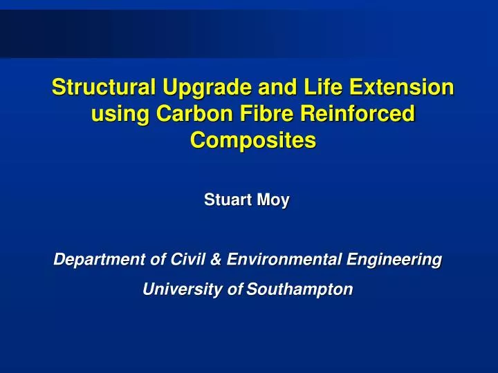
Structural Upgrade and Life Extension using Carbon Fibre Reinforced Composites Stuart Moy Department of Civil & Environmental Engineering University ofSouthampton
Research Partners • DML Composites • London Underground Limited • MSL Engineering • Structural Statics • DERA, Farnborough • Southampton University
Contents • 1. Description of cut and cover strengthening using a CFRP beam. • 2. Strengthening of cast iron struts using externally bonded CFRP.
Tunnel strengthening – the problem • The near surface tunnels of London Underground are over 100 years old. • They are supported by cast-iron girders that span the tunnel and by brick jack arches between the girders. • Over the years there has been development above ground and greatly increased traffic. The environment in the tunnels can be aggressive. • The cast iron girders need strengthening. There has been a girder failure.
PROTOTYPE 8m long 2.4m wide TEST BEAM 7.6m long 7.4m effective span 1.5m wide 0.4m deep Prototype and test beam comparison
Monitoring performance • Static test • Fatigue test • Coupon test programme – long term performance
Conclusions • Test beam stronger than predicted at ‘first failure’ and collapse • Test beam had slightly lower stiffness than predicted • Discrepancies due to difference between quoted and actual material properties • ‘First’ failure predicted inside the curved spar cap with damage gradually spreading in that region • This is generally what happened in the test although damage spread into the web of the ‘U’ shaped spar
Introduction to strut strengthening • Description of the strut problem • Outline of test programme • Results from the tests • Conclusions from the tests • Outline of the strengthening scheme at Shadwell station • General conclusions
Validation of CFRP strengthening scheme The problem • Struts are over 100 years old • Struts have an existing load which cannot be removed before strengthening • The struts are very large, any strengthening must cause minimum disruption to trains running below Possible validation methods • Theoretical studies • Finite element analysis • Testing
Testing 1. Preliminary tests on 12.2m long struts from Rotherhithe Carried out at NEL, East Kilbride Problems with local failures at the ends, but indicated benefits of using CFRP 2. Further Tests commissioned Aim: To investigate the benefits of CFRP reinforcement, even when the strut is preloaded before being reinforced
Details of the test strut section a) details of cruciform section b) location of reinforcement and strain gauges
Load - Deflection Curves Load – deflection curves for struts III/U and III/R
Conclusions from the Strut Tests • The bond between the carbon fibre composite and the cast iron was excellent, giving fully composite behaviour between the carbon fibre plates and the cast iron strut. • Even when there was a significant pre-load in the cast iron the application of carbon fibre reinforcement stiffened and strengthened the strut. These benefits were enhanced by the application of extra reinforcement.
Conclusions from the strut tests • The carbon fibre composite is usually needed to reinforce the cast iron that is in tension, however both sides have to be reinforced. In the tests the carbon fibre composite in compression failed first (as expected) but the reinforcement on the tension side remained fully effective until catastrophic failure of the cast iron in tension. The tests confirmed that the use of CFRP is an acceptable approach to the strengthening of in-situ cast iron struts.
Repair Method • Aim to reduce loads in existing struts, to increase their strength and to cause minimal disruption to the civils works • Additional steel jacks installed • Cast iron strengthened in-situ using ultrahigh modulus carbon fibre using RIFT technique • Validation completed in LINK and directly funded programmes • Project viewed as very important in enabling LUL to introduce lower cost repair techniques
Scope of Work • Shaft 13m x 34m • Total of 160 surfaces required strengthening • Total infused length approx 880 metres • Weight of composite added about 1.8 tonnes • Work completed in two phases - preparation and strengthening
Phase II works (Manufacture of stacks) • Carbon fibre pre-forms manufactured at DML, Devonport • High modulus carbon fibre woven to correct width in uni-directional tapes • Tapes are then cut to the correct length • Plies are built up to match thickness requirement • All consumables included in stacks • Stacks are stitched together and packaged for transportation • On-site processes then minimal and straightforward
Phase II Works (Installation) • Carbon fibre added to all four arms of cruciforms and to bracing • Fibre applied using RIFT technique • High quality composite formed • low void content • Full wet out and no dry spots • Repeatable and consistent • High bond strength • Up to 24 plies applied to arms • All work completed within 9 weeks by a team of 10 people
Post-Installation • After installation all beams were painted white to reduce heating from direct sunlight • The temperature increase in the cast iron beams and associated expansion is source of highest loads in the unreinforced struts • Inspection regime designed to build confidence in continuing fitness for purpose of strengthened beams
Lessons Learnt • Main objective to strengthen struts with minimum disruption to the operation of line and minimum disruption of 140 year old civils work achieved • Process of applying carbon on site was viewed as very flexible and simple • Problems included the level of surface preparation specified - research carried out in DML-led LINK programme to determine whether this can be relaxed • Concerns about effect of climate on resin cure proved unfounded. 12 hour cure to be reduced. • Lack of in-service track record now the major hurdle
Conclusions from strut programme • Ultrahigh modulus carbon fibre has been used to strengthen cast iron cruciform struts on 140 year old structure • Culmination of 4 years of research and development • Total strengthening amounted to nearly 1km of carbon, weighing nearly 1.8 tonnes
General conclusions • The two research programmes have demonstrated the potential of CFRP composites for the strengthening of cast iron structures. • Further work needs to be done on the CFRP beam. In particular the end supports and the installation procedure need to be sorted out. • The strut strengthening at Shadwell continues to perform well, monitoring continues.
Acknowledgement • The project partners are grateful to the DETR and EPSRC for funding the research under the Partners in Technology and LINK Inland Surface Transport Programmes.