Download
1 / 11
110 likes | 213 Views
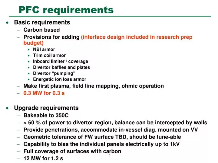
PFC requirements. Basic requirements Carbon based Provisions for adding (interface design included in research prep budget) NBI armor Trim coil armor Inboard limiter / coverage Divertor baffles and plates Divertor “pumping” Energetic ion loss armor

E N D
PFC requirements • Basic requirements • Carbon based • Provisions for adding (interface design included in research prep budget) • NBI armor • Trim coil armor • Inboard limiter / coverage • Divertor baffles and plates • Divertor “pumping” • Energetic ion loss armor • Make first plasma, field line mapping, ohmic operation • 0.3 MW for 0.3 s • Upgrade requirements • Bakeable to 350C • > 60 % of power to divertor region, balance can be intercepted by walls • Provide penetrations, accommodate in-vessel diag. mounted on VV • Geometric tolerance of FW surface TBD, should be tune-able • Capability to bias the individual panels electrically up to 1kV • Full coverage of surfaces with carbon • 12 MW for 1.2 s
PFC envelope maximized inside vessel • PFC envelope is pushed out to vessel wall to provide maximum plasma shape flexibility • Divertor envelope is still evolving, but baffles for neutral particle control must be accommodated PFC envelope PFC envelope with plasma
PFC design concept Poloidal ribs • Staged implementation planned • Initial coverage with carbontiles mounted on vessel assembly flanges to form array of poloidal limiters • Panels for NB armorand divertor region will also be provided after NBI installed • Full coverage provided by mounting molded carbon fiber composite (CFC) panels on poloidal ribs • Panel size based on advice from BFG aerospace (~ 60 cm square, 1 cm thick) • Ribs are separately cooled / heated with He gas for bakeout (350C) and normal operation • Ribs are registered toroidally to VV but allowed to grow radially and vertically CFC panels mounted on poloidal ribs
PFC panel / rib detail • Details for one concept for panel attachment developed with BFG Aerospace Plasma Panel installed Panel ass’y retracted Thermally insulated connection to vessel Heated / Cooled Rib Vacuum vessel
Project cost: Program cost: PFC implementation plan
PFC implementation: Phases I, II, III • NO Rib structure with cooling/heating lines • Carbon (e.g. Poco, ATJ) tiles mounted directly to VV • Carbon limiters are installed only at v=1/2 (bullet) cross section, but are semi-continuous poloidally
PFC simple limiter detail • Details for flat carbon plates at either side of bullet shaped section (vessel field joint) Plasma Spacer at bullet section Carbon plate Tee nut Joint stud Stand-off Vacuum vessel
Heat loads on limiter • Assume: • 1 cm e-folding of particle energy • 0.3 MW per pulse • 6 toroidal locations to remove heat • Poloidal peaking factor of 20 • Max flux = 2275 W/cm^2
Heat flux limit on isolated limiter tile • 1-D calculation • Ratcheting limit assumes radiation cooling only • 10 minute cool-down between pulses • 1200 C max temperature Operating point
Plasma (a) (b) PFC implementation: Phase IV • Rib structure with cooling/heating line • Panel coverage from upper divertor to lower divertor on inboard side • Panel coverage for NBI armor on outboard side • Exposed ribs protected with low Z coating: • B4C spray coating • Sheet metal covers with B4C coating
baffle pump (e.g. Ti-getter) divertor plate divertor pumping plenum First wall panel surface LCMS Z(m) PFC implementation: Phases V,VI • Phase V, divertor baffles • Phase VI, with active pump • Panel coverage everywhere? Ref. Peter Mioduszewski.