Download
1 / 52
520 likes | 669 Views
Microprocessor system architectures – IA32 advanced features and rests. Jakub Yaghob. Multiple-processor management. Mechanisms Support for atomic operations on system memory Serializing instructions APIC L2 and L3 caches Hyper-threading Aims Maintain system memory coherence

E N D
Microprocessor system architectures – IA32 advanced features and rests Jakub Yaghob
Multiple-processor management • Mechanisms • Support for atomic operations on system memory • Serializing instructions • APIC • L2 and L3 caches • Hyper-threading • Aims • Maintain system memory coherence • Maintain cache coherence • Predictable ordering of writes to memory • Distribute interrupt handling among processors • Increase system performance by exploiting multi-threaded OSs and applications
Locked atomic operations • Three independent mechanisms • Guaranteed atomic operations • Bus locking usingLOCK#or instruction prefixLOCK • Cache coherency protocols insuring cache coherency for atomic operations on cached data (cache lock) (Pentium Pro+)
Guaranteed atomic operations • i486+ • R/W a byte • R/W a word (2B) aligned on a word • R/W a dword (4B) aligned on a dword • Pentium+ • R/W a qword (8B) aligned on a qword • R/W a word from/to uncached memory within 32-bit bus • Pentium Pro+ • Unaligned word, dword, qword R/W from/to cached memory within a cache line
Bus locking • Automatic locking • XCHGwith memory • SettingB (busy) flag of a TSS descriptor • Updating descriptors (e.g.A flag) • Updating page tables • Interrupt acknowledgement • Software controlled locking (prefix LOCK) • Automatically assumed forXCHG • BTS, BTC, BTR • XADD, CMPXCHG, CMPXCHG8B • INC, DEC, NOT, NEG, ADD, ADC, SUB, SBB, AND, OR, XOR • Otherwise #UD exception (invalid opcode) • Memory access can be unaligned • Pentium Pro+ serializes locked operations
Self-modifying code • Option 1 • Write modified code using data segment • Jump to new code or an intermediate location • Execute the new code • Option 2 • Write modified code using data segment • Execute a serializing instruction • Execute the new code • Required for Pentium Pro+ • Performance penalty • Cross-modifying code • One CPU changes a code and the second one executes it • Synchronize CPUsand execute a serializing instruction
Memory ordering • Program-ordering • Alias strong-ordering • R/W issued on the bus in the order they occur in the instruction stream under all circumstances • i386 • Processor-ordering • Alias speculative-ordering or weak-ordering • Allows increased instruction execution speed, while maintaining memory coherency • The exact behavior depends on a model; Pentium Pro+ • Pentium and i486 • They use processor-ordering • In most cases they behave as program-ordered • R miss goes ahead of W, when all buffered W are cache hits • I/O always in the order of instruction stream (strong-ordering)
Processor-ordering I. • Single-processor and WB memory • R can be carried out speculatively and in any order • R can pass buffered W, but the CPU is self-consistent • W to memory are always carried out in program order, excluding instructions CLFLUSH, MOVNTI, MOVNTQ, MOVNTDQ, MOVNTPS, MOVNTPD • W can be buffered • W are not speculative; performed only for really executed (retired) instructions • Data from buffered W can be passed to waiting R within the CPU • R/W cannot pass I/O, locked or serializing instructions • R cannot pass LFENCE and MFENCE • W cannot pass SFENCE and MFENCE • Multiple CPUs • Individual CPUs behave as single-processor • Writes by a single CPU are observed in the same order by all CPUs • Writes from the individual CPUs on the bus are NOT ordered with respect to each other
„Fast string“ operation • „Fast string“ • Pentium Pro+ • MOVSorSTOS • CPU works with cache lines • Reads are not performed during cache line writes • Interrupts only on the cache line border • Conditions • EDIandESIaligned to 8B (PIII), EDIaligned to 8B (P4) • Ascending order (DF=0) • Initial counterECX>=64 • Source and target most not overlap by less then one cache line (64B forP4+, 32B other) • Memory type WC or WB
Strengthening or weakening memory ordering • Strengthening • I/O instructions, locked instructions, LOCKand serializing instructions • SFENCE (PIII), LFENCEandMFENCE (P4+) • SFENCE – all W finished before this instruction • LFENCE – all R finished before this instruction • MFENCE – all R and W finished before this instruction • PAT (Page Attribute Table) strengthens orderingfor pages (PIII+) • Weakening or strengthening • MTRR (Memory Type Range Registers) weaken or strengthenorderingfor physical memory regions (Pentium Pro+)
Serializing instructions • CPU finishes all flags, registers and memory changes • CPU clears all buffered W • Pentium+ • Privileged instructions • MOVCRx, MOVDRx, WRMSR, INVD, INVLPG, WBINVD, LGDT, LIDT, LTR • Non-privileged instructions • CPUID, IRET, RSM • Non-privileged for memory ordering • LFENCE, SFENCE, MFENCE
Propagation of page table entry changes • „TLB shootdown“ • Simple method • Send IPI to all CPUs • Stop all CPUs excluding one (spin-lock) • Active CPU makes the changes (invalidates page tables in memory) and resumes all CPUs • All CPUs invalidates their TLB (selectively or all entries) • All CPUs return from IPI • Complicated and faster methods can be developed • Different TLB mappings are not used on different CPUs during the update • The OS must be prepared for a situation where CPUs use stale mapping during the update
MPS 1.4 • Multiprocessor Specification • Controlled booting of multiple CPUs without a dedicated HW • HW can initiate a boot without a dedicated signal or a predefined boot CPU • All IA-32 CPUs have the same boot protocol (including HT) • Different mechanisms for different CPU models (P4 x Xeon older x Xeon newer) • BSP = Bootstrap Processor • AP = Application Processor
Detecting hyper-threading or multi-core • Hardware Multi-Threading feature flag • CPUID.1:EDX[28] = 1 • Logical processors per Package • CPUID.1:EBX[23:16] • Cores per Package • Only when CPUID works with EAX=4, otherwise it has 1 core • CPUID.(EAX=4,ECX=0):EAX[31:26]+1
Hyper-threading– I • One core is able to execute 2 or more instruction streams • Some parts of a core are private for each logical processor, some parts are shared among logical processors
Private state of a logical processor General purpose registers EAX-ESP (RAX-RSP, R8-R15) Segment registers CS-SS EFLAGS and EIP (RIP) x87 (ST0-ST7), MMX (MM0-MM7), SSE (XMM0-XMM7/XMM15) and their control and status registers Control registers CRx, GDTR, IDTR, LDTR, IA32_EFER Debug registers DRx Time stamp Most of MSRs (including PAT) Local APIC Instruction TLB Shared state MTRR Data TLB Cache, the bus Some MSRs Hyper-threading – II
Programming MT-capable CPUs – I • Requires support from OS • Using PAUSE instruction in spin-lock • Encoded as REPNOP • Older IA-32 CPUs interpret PAUSE as NOP • Older AMD CPUs do NOT understand it • UsingHLT • Idle logical processor must use HLT and must not actively wait • UsingMONITOR/MWAIT • SSE3, check CPUID.1.ECX[3] = 1, available only for CPL=0 • MONITOR sets up a memory range monitored for W • MWAIT places the processor in an optimized state until a W to the monitored range occurs
Programming MT-capable CPUs – II • Scheduling • Dispatch tasks to logical processors 0 for all cores, then to logical processors 1, etc. • Use thread affinity • Do not measure the speed of a CPU by an active loop • One lock or semaphore should be placed aligned into 128B block of memory
APIC (Advanced Programmable Interrupt Controller) • Local APIC • Internal in CPUs • Receives interrupts from CPU’s interrupt pins, from internal sources and from an external I/O APIC • Sends and receives IPI (InterProcessor Interrupt) • I/O APIC • Part of a chipset • Receives external interrupts and relays them to a local APIC • Possibility of IPI distribution among CPUs • xAPIC • Newer architecture • EXtended APIC • P4 and Xeons
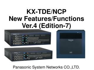
APIC – xAPIC • xAPIC system (P4 and Xeon)
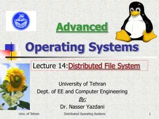
APIC – „traditional“ APIC • APIC system (Pentium and Pentium Pro+)
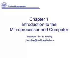
Internal cache • Cache structure of P4 and Xeon
Cache terminology • Cache use MESI protocol for maintaining coherency • Cache line fill • An operand is read from cacheable memory • The entire cache line is read • Cache hit • An operand is in a cache • An access uses a value from a cache • Cache miss • An operand is not in a cache • Write hit • If a valid cache line exists, CPU can write into the cache • If a write misses a cache, cache line fill occurs • Snooping • CPU checks memory accesses on the bus with its cache lines
MESI • Each cache line has 2 status bits • Transparent for programs • Instruction L1 has only SI • Transition by snooping • CPU detects W to the line with M • Cancel transaction • W line directly to the other CPU with branch to the memory • Moving to the I state
Cache control • CR0[CD] • =0 – caching enabled for the whole of system memory, can be restricted for regions or pages • =1 – caching disabled for Pentium, for other restricted • CR0[NW] • =0 – WB enabled, can be restricted • =1 –WB disabled • PCDandPWTin the page tables and directories • Disablecaching/WB for pages or page directories • PCDandPWTin theCR3 • Disablecaching/WB for page directories • Gin the page tables (Pentium Pro+) • Does not flush TLB entry during implicit flushing (task switch, mov cr3,eax) • CR4[PGE] (Pentium Pro+) • EnablesGin page tables • MTRR (Pentium Pro+) • Memory types for regions of physical memory • PAT (PIII+) • Memory types for pages
Store buffers • IA-32 stores temporarily each W to memory in a store buffer • CPU continues without waiting on the memory or a cache • Transparent forsoftware • Draining store buffers • An interrupt or an exception • Serializing instruction (Pentium Pro+) • I/O operation • LOCKoperation • BINIT operation (Pentium Pro+) (machine check) • SFENCEinstruction (PIII+) • MFENCEinstruction (P4+)
Memory types – an overview • Pentium has UC, WT, WB • Control using NW, CD • UC- from PIII with PAT
Memory types – I • Strong uncacheable (UC) • The system memory is not cached • All R/W havestrong-ordering, no speculation • Useful for memory-mapped I/O • Greatly reduces system performance • Uncacheable (UC-) • Like UC, can be overridden to WC using MTRR • Only PIII+using PAT • Write Combining (WC) • The system memory is not cached • No coherency protocol • Speculative R enabled, W ordering isNOTensured • W delayedandcombined in WC buffers • Useful for video framebuffers
Memory types – II • Write Through (WT) • R/W from/to the system memory cached • R comes from a cache on cache hit; cache line fills on cache miss; speculative R • W writes to a cache and the main memory on cache hit; does not write to the cache on cache miss • WC enabled • Useful for video frame buffers or devices without snooping • Write Back (WB) • R/W from/to the system memory cached • R comes from a cache on cache hit; cache line fills on cache miss; speculative R • W writes to a cache and the main memory on cache hit;cache line fill on cache miss • Cache coherency protocol • Write Protected (WP) • R comes from a cache on cache hit; cache line fills on cache miss; speculative R • W directly propagated on the system bus
MTRR (Memory Type Range Registers) • Assigning memory types to the physical memory regions • Checking MTRR presence usingCPUID • MSR R/O registr IA32_MTRRCAP • Support for fixed ranges • Number of variable ranges (Pentium Pro+) • Support for WC type • Default type • MSR IA32_MTRR_DEF_TYPEdefines memory type for physical memory not covered by fixed and variable ranges • Fixed ranges • 8 rangesof 64K size in the lowest 512K (00000000-0007FFFF) • 16 ranges of 16K size in the next 256K (00080000-000BFFFF) • 64 ranges of 4K size in the next 256K (000C0000-000FFFFF) • Variable ranges • Address&PHYSMASKn = PHYSBASEn&PHYSMASKn • When a variable range overlaps with a fixed range, the fixed range wins
PAT (Page Attribute Table) • Assigning memory type to the ranges of linear address space • Checking PAT presence using CPUID • MSR IA32_CR_PATdefines 8 types • The type for a page is selected fromIA32_CR_PATby an index created from PAT(4), PCD(2), PWT(1) bits in page tables • It is always switched on • The initial setting after RESET is backward compatible withPCDandPWT – 2 * (WB, WT, UC-, UC)
Memory types restrictions • IfCR0[CD]=1, then caching is disabled • IfCR0[CD]=0, then caching restricted using PAT (orPCDandPWT) and MTRR • Always selected the most restrictive type • WT „wins“ over WB • WC „wins“ over WT and WB
Reset • Sets a CPU to the well known state • CPU in the real mode • Internal caches, TLB and BTB invalidated • CPU model dependent behavior • Pentium Pro+ • All CPUs start initialization protocol, on of them is chosen as BSP and continues in an OS initialization, all other APshalt and wait for an IPI „Wait for Startup“ • i486 and Pentium • HW knows, which CPU is BSP, other APshalt and wait on SIPI • INIT • Like RESET • Internal caches, MSR, MTRR, x87, SSE do not change • Move to the real mode
Microcode update • Pentium Pro+ has an interface for uploading microcode block with patches to the CPU • Microcode block is supplied by Intel directly to the BIOS vendors • Microcode block has a header with CPU model specification • Checking CPU model in the microcode header with current CPU • A microcode must be uploaded before L2 is enabled and lot of other constraints (e.g.segment limit exceeding)
Virtual machine extensions (VMX) • Two classes of software • Virtual machine monitor (VMM) • Acts like a host • Full control of HW • Presents abstract HW to guests • Guest software • Guest software environment with OS and applications
Virtual-machine control data structure (VMCS) – I • VMX non-root operation and VMX transitions controlled by a VMCS • Access through the VMCS pointer (one per logical CPU) • Changing the pointer using VMPTRST and VMPTRLD instructions • VMCS configuration using VMREAD, VMWRITE, VMCLEAR instructions • VMM could use a different VMCS for each virtual CPU • Each logical CPU associates a physical memory region (one 4KB frame) with each VMCS
Virtual-machine control data structure (VMCS) – II • VMCS state • Inactive • after VMCLEAN • Active • Memory region after VMPTRLD • Maintains CPU state • Current • VMPTRLD loads current VMCS • VMLAUNCH, VMPTRST, VMREAD, VMRESUME and VMWRITE operate with current VMCS
Virtual-machine control data structure (VMCS) – III • VMCS data • Guest-state area • CPU state is saved on VM exits and loaded from there on VM entries • Host-state area • CPU state is loaded on VM exits • VM-execution control fields • VM-exit control fields • VM-entry control fields • VM-exit information fields
Guest-state area • Registers • CR0, CR3, CR4 • RSP, RIP, RFLAGS • CS, DS, ES, FS, GS, SS, LDTR, TR • Selector and part of internal cache • GDTR, IDTR • MSRs • IA32_DEBUGCTL, IA32_SYSENTER_CS, IA32_SYSENTER_ESP, IA32_SYSENTER_EIP • Activity state • Active, HLT, shutdown, wait-for-SIPI • Interruptibility state • Blocking by STI, MOV SS, NMI, SMI • Pending debug exceptions • VMCS link pointer
Host-state area • Registers • CR0, CR3, CR4 • RSP, RIP • CS, DS, ES, FS, GS, SS, TR • Base address for FS, GS, TR, GDTR, IDTR • MSRs • IA32_SYSENTER_CS, IA32_SYSENTER_ESP, IA32_SYSENTER_EIP
VM-execution control fields • Pin-based VM-execution controls • VM-exits on external interrupt or NMI • CPU-based VM-execution controls • Instructions and events causing VM-exits • Exception bitmap • I/O-bitmap addresses • Guest/host masks and read shadows for CR0 and CR4 • CR3 target controls • 4 target addresses+counter • CR8 access control • MSR bitmap address
VM-exit control fields • VM-exit controls • Basic operation of VM-exit • VM-exit controls for MSRs • List of MSRs stored and loaded on VM-exit
VM-entry control fields • VM-entry controls • Basic operation on VM-entry • VM-entry controls for MSRs • List of MSRs to be loaded on VM-entry • Event injection • “Executed” before the first guest-mode instruction • Interrupts, exceptions including error-code
VM-exit information fields • Basic VM-exit information • Exit reason, exit qualification • Vectored events • Interrupts, exceptions • VM-exits during event delivery • VM-exits due to instruction execution • Instruction address, length, detailed information
VMXON region • Physical memory region (4KB frame) for VMX operation • Operand of VMXON instruction