Download
1 / 19
190 likes | 335 Views
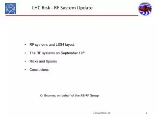
Operation experience with the LHC RF system. Prepared by O. Brunner and L. Arnaudon/ CERN on behalf on the RF group CW RF Workshop / Alba, Mai 4-8 2010. Summary. Presentation of the LHC RF system First results with beam Reliability and performances. Layout (1). Two independent rings

E N D
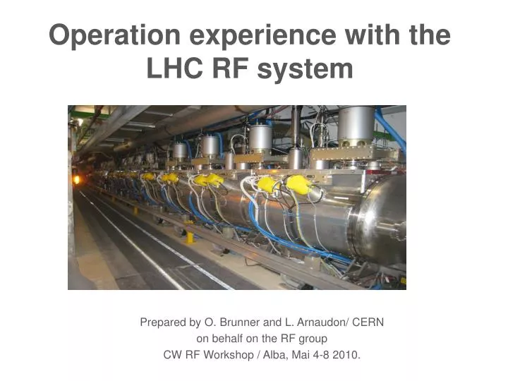
Operation experience with the LHC RF system Prepared by O. Brunner and L. Arnaudon/ CERN on behalf on the RF group CW RF Workshop / Alba, Mai 4-8 2010.
Summary • Presentation of the LHC RF system • First results with beam • Reliability and performances
Layout (1) • Two independent rings • 8 RF cavities per ring all installed at point 4 • Klystrons and Cavity Controllers in a cavern ~150 m underground
Layout (2) • 100kV, 40A (ex-LEP) power converters located at the surface • Klystron modulators, fast protection systems in four HV bunkers • Sixteen 330 kW klystrons + circulators + RF ferrite loads in UX45 • Power control system based on industrial PLCs, plus a fast Interlock protection system • WR2300 HH WG distribution system to individual cavities • LLRF for Cavity Controllers in two Faraday Cages • Beam Control equipment in a surface building in SR4 => Most of RF equipment is not accessible during operation
HV power converters • 100kV, 40A (ex-LEP) power converters located at the surface • Each power converter feeds 4 klystrons • Nominal klystron working point: 58 kV, 8.8A (now 50 kV, 8A, see below) • Main concern: RF noise in cavities due to HV rippple • Klystron HV is produced by 12 poles => HV contains ripples at 50, 100, … and 600Hz producing phase modulation of the RF output • Up to 10% HV ripple measured on power converters @ 58kV, 36A • Could be reduced to ≈ 0.5 – 1% by fine tuning the phase advance of 12 phases to minimize HV ripple • HV ripples: 1 % variation of HV still induces ≈8 degrees @ 400.8MHz and 58kV • Still an issue since 50Hz close to LHC synchrotron frequency • Klystron Polar Loop => down to ~0.2 dg pkpk P. Baudrenghien, The LHC Low Level RF, LLRF07, Knoxville TN, Oct 23,2007
Klystron CW (1) Pout Clamped (SWAP) Operating point ≈-1.5dB below saturation • 1 klystron per cavity • 330 kW max (58 kV, 8.4 A) • 130 ns group delay (~ 10 MHz BW) • CW gain 39 dB @ 200 kW, 36 dB @ 300 kW • In operation ≈ 200 kW CW Pin Klystron power sweep CW @ 400.8 MHz
Klystron CW (2) • LLRF constraints: • Systems typically operated at a peak output power ≈ -1.5dB below saturation (@f0) plus a ≈20dB lower superimposed correction signals between f0 +/- 6 MHz. => sets the maximum admissible gain for the klystron’s bunching cavities as a function of frequency • LHC: Notch filter integrated in the LLRF to cope with the second bunching cavities • all klystrons second bunching cavities tuned in same frequency range (+/- 0.4 MHz) • resulted in quite poor klystron efficiency in some cases.. Klystron low signal sweep f0 +/- 6 MHz Klystron peak output power ≈ 200kW @ f0 plus a ≈20dB lower superimposed sweep signals between f0 +/- 6 MHz
Klystron CW (3) • 21 klystrons @ CERN • 16 in LHC • 2 on test stands • 3 spares • Problems so far: • 1 klystron developed a short circuit in gun (repaired) • 1 klystron with sudden overheating of the output coaxial transition (multipactor) • 1 klystron died due to a vacuum leak after 16 khrs • Bad water cooling of the hypervapotron collector was found culprit • Water cooling jacket modified and successfully tested (>48hr full DC power test) • At the time, all klystrons were equipped with modified water cooling jacket • Post inspection of at least one LHC collector was planned (>1000hrs) • Inspection in LHC took place in January ’10 • Reveal that the new boilers did not solved the problem! • Collectors are still overheating • Simulation from Thales showed that the collectors are suffering from a deficiency in water speed in this region • Campaign launched with THALES to find a definitive solution… • In the mean time…as LHC had to be restarted in February • DC power limited to 400kW max (50kV, 8A) (instead of 58kV , 8.5 A) • Water flows inverted on all collectors, to get better water speed homogeneity
Circulator, RF load, WG - 1 circulator per cavity • 330 kW max • 60 ns group delay • Circulator equipped with temperature control system • Affects the Qext of the cavity (=> see N. Schwerg’s presentation) -1 RF ferrite load per circulator • 330 kW CW • RF loads reflection < -28 dB - Wave guide system • WR2300 HH • Length: 15 to 30 meters
Cavities • 8 RF cavities per ring at 400.790 MHz: • Super Conducting Standing Wave Cavities, single-cell, R/Q = 45 ohms, 6 MV/m nominal • Equipped with movable Main Coupler (20000 < QL < 180000) • Mechanical Tuner range = 100 kHz • 4 spare cavities assembled in a cryomodule + 1 spare cavity • new spare cavities shall be built in the next years
Cavity controller: • Fast loops using cavity or waveguide measurements • Individual control: • the field in each cavity • the cavity tune • the klystron gain/phase shift L. Arnaudon • The Klystron Polar Loop compensates for the klystron gain/phase changes • The RF Feedback Loop reduces the cavity impedance at the fundamental. • The Tuner Loop minimizes the klystron current.
Beam Control • the average energy of the beam (via the RF frequency) • the phase of the average voltage (vector sum of 8 cavities). • The Frequency Program: • Generates an RF which is set to the injection frequency and then follows a function through the acceleration ramp • Phase loop: • Locks the Cav Sum (RF sum of the Antenna of 8 cavities) onto the beam (Wide-Band PU signal thru 400.8 MHz BPF) at injection. • Very fast loop. Reacts in ~ 10 turns (~ 1ms). Must be fast compared to synchrotron period (Ts around 20 ms) to avoid filamentation at injection. • Synchro loop: • Locks the RF on the Frequency Program. • The Freq Program reference is sent to the SPS (ref for injection) and is the common ref for both rings (ref for cogging). • Slow loop. Reacts in tens of ms L. Arnaudon
RF Synchronization: • Pilots the bunch into bucket transfer from SPS to LHC • A very flexible system allows operation to inject in any bucket using the bucket selector application. • The collision point is set and kept very precisely within specification, 2mm in an optimal range of 30mm. • No correction of the setting since 2 month and no difference related to energy change. J. Noirjean 92 fiber optic link are used to distribute frequencies and synchronization pulses between LHC, experiments and the CERN accelerator complex.
Capture (1) T. Bohl / U. Wehrle RF ON, good phase Phase loop OFF… RF ON, good phase Phase loop ON… RF ON, wrong phase… Mountain range displays
Couplers gymnastic • During physics: • Emittance must be blown up to 2.5 eVs (lifetime issues) => 16 MV needed • High QL required (2 MV/cavity) • At injection: • 8 MV to match the 0.8 eVs bunch from the SPS • Low QL favorable for fast damping of momentum/phase errors First move Q to 60k then raise voltage
Reliability and performance (1) • Beam intensity: • Pilot beam with low intensity (2E10) and low emittance (0.2-0.4eV) • Successful tests made with one bunch at nominal intensity (1.1E11) & emittance up to 2.5eVs • > some very long physics fills @ 3.5 TeV • Luminosity lifetime of up to 30h • Limitation: 50kV, 8A • Reliability: • 0 hrs of beam lost due to RF • Few trips per day/week • Some recurent problems successfully treated • Thyratron auto triggering • Arc detectors • Main coupler blower glitches: still an issue under investigation
Reliability and performance (2) L. Arnaudon • RF system consists of about 1000 interlocks • Long periods (>>days), without RF trips. • The RF system is very reliable with the present beam conditions, efforts will continue to prepare for the higher intensity runs…